(The story is a conversation.)
5/2 
Last night, during my knob twiddling on the AM band, I ventured into the no-man's land above 1300 kHz where all the locals are. It's like a desert up there. With the exception of KOMA on 1520, which must have been grandfathered in at some point, and our own local, no stations are listenable. I have never really given it much thought. It's what would one expect, right? - the locals are limited to a few hundred watts. Anyway, I took a listen on 1660 kHz where KXOL in Salt Lake City resides. Ditto, unlistenable. Now wait a minute(??). Shortly after we bought this house in '99, before we had moved in, I spent evenings out here fixing up the place - and listening to KXOL, clear and almost without fading. (I remember thinking at the time: All right, a station I can listen to - solid music with almost no commercials!) But, what the heck happened in the meantime?!
Trying to hear KXOL brought back a question that has always nagged me a little: How could those 250-watt old-timers back in the '20s and early '30s be so widely heard!?
The answer to both questions is the same. The 'silence' we hear on the local channels isn't really silence, it's the cacophony produced by the hundreds - thousands? - of stations occupying that part of the band. It comes through as an almost-white noise. When KXOL was one of the first stations to venture into the newly-opened 1600-1700 kHz part of the band, it had the place all to itself! Of course it would be widely heard, just like the pioneers of early radio. As the band filled up with more stations - then and now - individual stations became lost in the mud. The power wars of the early days were halted when the FCC created the three classes: local, regional and clear-channel. The locals are just that. Unless one is some kind of DX chaser, willing to sit on a frequency waiting for some station to fade in enough to pick up the ID needed for a contest record or something, those frequencies are useless to people who actually want to listen to the radio in the middle of the night. So, except for that soothing white noise-like sound that puts me to sleep, it's back down to the lower regions of the band for me.
5/2
> Perhaps the Low Power crowd should try for LPAM.
Might work in the daytime. At night forget it, unless you consider 250 watts 'low-power'. A local needs every watt of that to overcome the skip coming in from the dozens (scores, hundreds?) of stations operating on the channel. A class-C (local) FM actually has better coverage, watt-for-watt (transmitter output) at night, than does an AM local.
> I know the AM xmitters are less elegant,
Hmm.. not the modern ones. Fairly sophisticated digital phasing techniques are used nowadays in AM transmitters, mostly with the goal of better energy efficiency. The technique of full-carrier single-sideband is a big energy saver. True, the result at the receiving end is still the same old AM signal we all know and love.
> pain in the ass to build and
> operate,
Multiple-tower transmitters are a pain to operate; single tower ones less so. Locals are almost always of the latter variety.
> Perhaps you should put together a 20 Watt or so AM
> xmitter and see if it flies.
> You could put it at the
> very bottom of the band
Now that you mention it, 530 and 1610 (maybe 1710 now) are reserved for low-power informational services - road construction, parks, etc. A 100-watt AMer would probably do quite well on one of those. But, as you said, AM is more of a hassle. [I'd probably do it the old fashioned way, an audio power amp driving a modulation transformer.]
I remember hearing the information station at Stapleton airport in broad daylight for about 15 minutes one day as I was driving my company truck here in this area [170 miles distant]. That experience again points out the incredible propagation characteristics of the AM band, largely invisible nowadays because of the large number of stations occupying the band.
> A 50 foot base
> loaded antenna with a top hat would just about handle
> the antenna requirement.
Such antennas are useful in a number of ways, on a number of bands. If I ever re-acquire fire-in-the-belly for radio experimenting, I might consider putting mine back up.
5/3
Now that I think of it, that 150-watt PA amplifier you gave me would make an almost perfect modulator for a 300-watt AM transmitter. It already has the transformer! Why'n't you design up and build a nice 300-watt class-C RF power amplifier that operates on 530 or 1710 kHz for me? Solid state would be nice, but hey, tubes will do. The transformer on that PA amp has taps up the wazoo. One could probably match it to almost anything.
5/4
> However, you can't run class C PA's on AM.
Sure you can. It's called 'high-level' or 'plate modulation' and it was how things were done before the digital techniques became common. You have an oscillator, a buffer stage, and a final, all operating in class-C mode. The modulation power, supplied from a high-powered class-AB audio amplifier, is coupled to the final through a modulation transformer in series with the plate DC supply. The audio voltage adds to (or subtracts from) the plate voltage, amplitude modulating the output signal.
> They sound
> like crap.
They sounded good and probably accounted for some of that distinct 'AM sound' some of us remember from our youths.
5/5
> I just reread the info in the Radio Amateur's
> Handbook, which I suppose is where I've gotten all of
> my info on amplifier classes and modulation modes.
I haven't read one of those recently. I suspect AM gets very little mention anymore. Plate modulation was THE modulation method for the 50 years before SSB overtook AM for voice communications (commercial and amateur) and broadcasting. I think it is still fairly common in short-wave broadcasting. I've seen pictures of the modulation transformers used in some of those old 500 kW transmitters. They were huge, and must have weighed tons.
> They still say that Class C isn't linear enough and
> should be reserved for FM and CW.
I'm sure that refers to a downstream amplifier - in the system after the modulator. When SSB came along so-called 'linear' amps (usually class AB), for attachment between a transmitter output and the antenna, became common. These could be used on CW/FM, AM or SSB. Interestingly, the power ratings for a linear amp are different for the different types of modulation. An amp rated for 2 kW (peak envelope power) for SSB would be good for only 500 watts (or less) on AM. Some of the 9 dB advantage of SSB over AM is lost in the lower efficiency of the final.
I also find it interesting that the newer 'digital' modulations modes (16QAM, 256QAM, etc.), which are actually hybrids of PM and AM, require a linear final, unlike 'analog' FM which, as you point out, gets by with a class C final.
A modern AM transmitter is actually a digital device and some designs use PM - in the final - to generate an AM signal efficiently.
> class C power amps that wouldn't make sense in
> low power amateur applications.
I remember in the early '5-watt' AM-only CB sets, the receiver's audio power amp did double duty as the modulation amplifier; the audio output transformer became the modulation transformer in the transmit mode. I suspect the $49.95 AM sets sold during the craze used a similar technique.
5/5
Yeah, I've been thinking some more on the AM idea. A transmitter could be built with as few as 3 tubes, but who wants to fool with tubes? A better way, I think, would be to use power MOSFETs. By operating the final(s) at 100 volts DC on the drain(s), 3 amps of drain current would be good for 300 watts and be a made-in-heaven match for the 70.7-volt RMS tap on the output transformer of the 150-watt audio amplifier you gave me. [70.7 vRMS = 200 vPP; voila, 100% modulation!] However, a consideration that may make the transformer unsuitable for modulation service is the need for it to carry the DC for the RF amplifier's plate [drains] in addition to the audio power without saturating or overheating from ohmic losses. The 70.7 volt secondary tap of the audio amp measures 1.6 ohms resistance, which means that, with 3 amps of DC plus the worst-case 2.14 amps of AC (audio) flowing, the transformer secondary would drop about 8.2 volts and cause about 42 watts of heating. Add that to iron losses and ohmic losses in the primary and it's going to get pretty hot. Too hot.
OK, so we back 'er down to 70.7 watts; 35.35 volts on the drain(s) at 2 amps. Now the 25.2-volt secondary tap comes real close to a match. [25.2 vRMS = 70.7 vPP; 100% modulation.] The 25.2 volt tap measures .5 ohms. 2 amps DC plus 1.4 amps AC across .5 ohms comes to about 6 watts. MUCH better. The RF amp would tool along at 70.7 watts, and the audio amp, at 35 watts, would be hardly working at all.
A real-world experimenter such as myself would probably just build a nice heavy-duty RF final stage, connect it to a variable DC supply, and run as much power as he could get away with while playing with the gain and taps on the modulation amp - trying hard not to burn it all up before deciding on reasonable settings.
How would it do? It would depend a lot on the frequency. On a clear channel it might be heard a thousand miles away. On one of the regular AM channels it might be heard as far as the city limits.
Another thought on transmitters. One could acquire one of those old 100-watt CW HF transmitters used by novice hams back in the 1950s. Those things were the starter systems of the day. As I recall, the novices were limited to 100 watts and CW on some restricted rock-bound HF frequencies. Again recalling.. the second step, after getting the General license was to wire up an audio amplifier of some kind to the transmitter, giving the unit AM capability and allowing the ham to actually TALK in the air!
If, in your travels and dealings at the swaps etc., you happen to come into possession of one of those things - Heath, Knight, Eico and many other companies sold them - I would be interested in converting it for AM operation on 1710 kHz. A unit that would tune up on 160 meters (1.8 kHz) would require little if any modification.
5/6
> Hams think in terms of plugging one box, a
> transmitter, into another box, an amplifier.
There is quite a bit of practicality in that approach: build on what you have.
> I sort of like the idea of paralleling old TV
> horizontal output tubes, but that's just nostalgia
> talking.
It's fun to think about the old technology, but I suspect it turns off younger people who view all the old modes like we might view a Model-T Ford or horse-drawn buggy, fit for a museum and not much else.
> I do have an old Lafayette(?) or Heath, rock bound CW
> xmitter in the front room. I'll take a look at it and
> see what bands it might cover. But I know that the
> Novice class operators it was designed for weren't
> allowed on 160 meters. Anyway I'll look into it.
Don't sweat it too much.
5/7
> That xmitter I have in the front room is a Heath
> HW-15. Unfortunately it also has the matching
> receiver, which makes it substantially more valuable,
> or at least a little more valuable,
Yeah, I wouldn't need the receiver associated with the Heath HW-15, and I wouldn't want you to split up the pair. That's OK, you may run into another old transmitter sometime. I'm sure there must be thousands of them gathering dust in attics. Or I can always try eBay. It's one of those projects that will fall together someday. I have the transmitting antenna and the modulator; when a suitable transmitter presents itself, the thing will happen.
As you know, as the frequency goes down, the hardware gets bigger. Bigger is more expensive. Makers of those things could cut costs significantly by not including the bottom band (or is it the top band?).
5/9
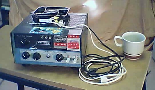
I checked out the public address amplifier you gave me on the bench. The rear of the unit says it's rated at 150 watts. That must be a peak rating or something. Continuous undistorted RMS power output is closer to 75 watts. That's OK. The available transmitters are all typically in the 50-100 watt range, so 75 watts of audio would be perfectly adequate. I see a '60s vintage Globe CW transmitter for $9.99 early in the bidding on eBay. As you mentioned, 160 meter coverage is rare on those things, but for $9.99 I sure could afford to mess it up a little converting it to 1710 kHz. Will think on it.
5/10
> The point there was that it is an xmitter that was
> intended for novices, so it only covered the legal
> novice bands, and 160 wasn't one of them.
Makes you wonder what the reasoning behind that (no novices on 160) was. It may have just been a matter of available spectrum. The tech licensee of today has access to much more spectrum than the novices of old. My guess is the 'novices' of those days were probably more technically savvy than the codeless techs of today. Or they became so darned quick; I would think you'd have to have a pretty good feel for the principles involved just to get one of those old transmitters on the air without burning holes in the plates of the finals. Then again, maybe the tubes installed were over-rated enough to prevent that.
The Globe CW transmitter is still up on eBay for $9.99, with no bids. I may go for it.
5/11
> Believe it or not, if I got this right, there was a
> time when 160 was the premier band,
Somehow I have the idea that the band is, or was, a bit of a hangout for AM holdouts.
***
> It [the HV switch on an HF transmitter I was tuning] was
> for conserving the hours on the expensive PA tubes
> while one was just listening to the receiver,
Yeah, that sounds reasonable. I suspect that the finals in amateur transmitters are a bit under-rated in order to save some money in their manufacture. Another possibility is the need to delay the application of the plate voltage until the cathode is fully heated. Same deal: to preserve the tube - the cathode can be damaged otherwise.
I just submitted my first bid on eBay - $9.99. Tegan showed me how. It turns out I already have a pretty good reputation on there. Anna, for some reason I can't remember now, did all of her early transactions using an account set up in my name and apparently didn't stiff anyone.. Actually, with PayPal I think the advantage is back on the sellers in these deals. About all the buyer can do is rely on a vendors' feedback.
> I don't know if it has any collector value or not, and
> the rattier it looks the better.
Looks pretty ratty. It'll look rattier after I'm done with it.
> Nice looking old
> stuff can draw a pretty good price from some of these
> old timers.
I've been looking around a little - learning about old Johnson Viking Valliants and other macho gear.
> And there is actually a resurrection of
> AMers growing on the ham bands.
OK! I knew I got that idea from somewhere - you!
5/13
Well, I bought a transmitter, the 90-watt Globe [HG-303], for $9.99. Now to get it here..
5/14
> Hurray on the $9.99 Globe!!!! (It must have looked
> real ratty.)
I shall find out. It might be a jewel in the rough, or a piece of junk.
> Now to paying $25 shipping and you're all set. Except
> for the minor difficulty of turning the whole shebang
> into an AM transmitter. Sounds like fun to me. And you
> did say you'd take your FM station off the air, but
> this ain't your FM station. :)
I gotta think now about re-stacking my 50' vertical. I'm not sure what kind of schedule I'll maintain with the AMer - might play one CD and then go silent forever. It looks as if there could be some activity on 1720. Makes some sense, although I don't think digital radios tune to that freq. Maybe that's the point.
5/17
Looking forward to getting my 'new' transmitter. The guy says he'll ship it for $10.
5/18
> Just $10 to ship that xmitter sounds like a deal, even
> if it's more than you paid for it.
Unless I get stiffed - always a possibility.
> Where is it coming
> from,
Selma, California
5/18
> not a beat up
> old Globe boat anchor
You callin' my Globe a boat anchor? It ain't nice to call my Globe a boat anchor. Don't bother me none, but, y'see, it hurts his feelin's.. Make 3 coffins...
Clint
5/19
> Yes, suh! I'll make 'em outta the best damn pine wood
> money can buy, suh!
After I sent that I got to thinking: I sure hope he saw that movie! Obviously you have.
5/24
I always thought of non-sanctioned broadcasting as more a technical challenge rather than a way to fulfill a desire to talk on the radio or provide a public service. FM is perfect for it: Modulation easier, antennas smaller, range better at low power. AM might appeal more to a technical geek.
No sign of my 90-watt blowtorch here yet. Guess I better rattle that guy's cage a little.
5/24
[Chris, Have you received the money order for $19.99 for the Globe transmitter yet? Item #2529177260. Thanks, Max Carter]
5/25
The guy in California with the Globe transmitter says he shipped the thing. Keeping my fingers crossed.
5/26
> I hope you soon get the entire Globe all for yourself.
I had forgotten where Globe equipment originated: The old World Radio Laboratories in Council Bluffs. Globe was spun off as a separate company in the late 50s and later absorbed by Textron. (WRL's other name, Galaxy, became Hy-Gain about the same time.) The HG-303 - the unit I bought - has been described as "one of the last-if not the last-CW-only, crystal controlled transmitters designed". Will see.
[The real boat anchor of WRL's line (I read) was the Globe King 500 AM transmitter at some 250 pounds of iron, steel, copper and glass.]
> I have a great big tube checker
> still down at the shop in Vernon if you need any tubes
> checked out,
Great! I threw away my tube checker when we moved in '99.
> although some RF output tubes probably
> won't be testable on it.
The final on the HG-303 is a 6146.
5/26
> I'm picturing your bench all
> aglow from the light of tubes in the dark. So much for
> heating the shop with gas. You're about to go
> electric.
Absolutely. I must get into the spirit of the thing. I'll be driving the Globe with my Knight (tube) signal generator as the VFO, using as a program source my Tandberg 64x (tube) reel-to-reel and, of course, monitoring modulation with my Heath IO-18 (tube) oscilloscope. Gotta find an old Gates (tube) mixer somewhere.
Kidding aside, that little transmitter is going to look funny sitting on top of its big modulator. I doubt the Globe can sustain its rated 90 watts at 100% duty cycle. My guess is I'll be lucky to get 50 watts out of it on a full-time basis. The transmitter will be huffing and puffing while the modulator loafs.
I may be getting in over my head here. A more sensible approach to this recently acquired desire to add AM would be to simply buy an old broadcast transmitter. I'll bet one could be obtained dirt cheap by being at the right place at the right time - like at the back door of a station as they're getting ready to load their old transmitter for its trip to the dump.
5/29
I have yet to see the transmitter from the guy in California who supposedly had already sent the thing when I queried him about it last Saturday. I'm beginning to smell a rat.
> I can't imagine the deal with the Globe being a scam.
Probably not a scam, just a guy that didn't get as much in the auction as he thought he should, even though he got his minimum bid. He may have decided to keep the $19.99 and toss the transmitter in the trash. I'll give him another couple of days and then bug him some more.
6/1
[Chris, I still have not received this item - Globe transmitter. When was the item shipped? By what method (UPS, USPS)? Any other details (tracking number, etc)? BTW, I'm willing to reimburse your shipping charges in excess of the $10 you quoted after I receive the item. Thanks, Max Carter]
[yes sir,and it's on it's way,thanks]
6/3
I finally got the Globe. It's a cute little radio. [Heavy though. I offered to reimburse the seller for the shipping charges above the $10 he quoted; I'm sure it cost more than that to send it.]
Now to see if it works. At $9.99 I wouldn't be surprised if it didn't, but I'm sure there's enough in there to enable me to rehabilitate it. I need to scare up 2-3 dozen 2-watt carbon resistors to build up a dummy load.
I just got an email from the Globe's former owner saying the shipping's on him. Now, it's on to some [modifyin']!
6/5
> I have one of those paint can dummy loads somewhere.
> Would you like me to send it out?
Absolutely. I think those are filled with oil, so it'll have to be packed very well (or drained); and whatever you do, don't tell the clerk at the post office that it has oil in it!
Globe report:
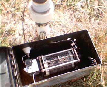
The RF deck appears to be undisturbed and of conventional design. The circuit uses 2 tubes, a 6CL6 oscillator and a 6146 final. According to the tube manual, the 6CL6 is a power pentode used typically as a TV vertical output. The crystals meant for this transmitter are those big old FT243s; a crystal for 4397.5 KC was plugged into the unit. Those are usually driven pretty hard as I recall - they would get noticeably warm in operation - thus a power tube could be used as both the oscillator and driver.
The 6146 is of course a tube known and loved for 25 years in everything from military gear to the finals in FM 2-ways to audio amplifiers.
The power supply is a disaster; extensively modified. It looks like the filter capacitors have all been replaced, sloppily. There is a socketed 0A2 regulator tube actually lying in there sideways without benefit of being mounted in the chassis - can't imagine that being a factory deal. There also appear to be some silicon diodes, can't tell if they were added. I don't think I'll be powering this any time soon and probably will pull most of that stuff out and attempt to rebuild the PS to a conventional design. The stenciling on the rear of the unit indicates the power supply puts out 600 volts. That sounds about right. Full scale on the plate current meter on the front panel is 160 mA. It tracks - 600 volts x 150 milliamps = 90 watts.
6/6
Thoughts on the Globe AM conversion:
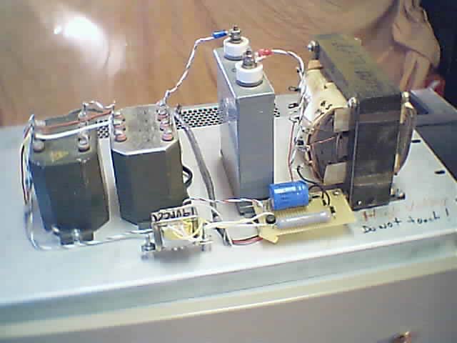
My modulator (the public address amplifier you gave me) is not well matched to the 90-watt transmitter's 600-volt power supply. The amplifier puts out a little over 200 volts peak-to-peak (at its 70-volt output terminals). BUT, I happen to have a couple of 25-watt line transformers from a public address system (these are ordinarily used in step-down mode to get the line voltage down to voice coil level) and by correctly series/parallel wiring these transformers and connecting to the 8-ohm output terminals of the amplifier, I can easily produce 500 volts RMS (1400 volts peak-to-peak) of audio across a 5000-ohm load (the approximate DC impedance at the plate of the 6146). This works out to 50 watts RMS.
[Linear amplitude modulation depends on the 'voltage squared' law: doubling the plate voltage causes the power to quadruple. 100% modulation is defined as a doubling of output signal voltage - a quadrupling of power - on positive peaks while output voltage drops to zero on negative peaks. I'm not sure if all RF output tubes strictly obey the voltage squared law but if the 6146 does, a 600 volt plate supply would require the modulator to output 1200 volts peak-to-peak for 100% modulation.]
[Assuming the RF output spends about half the time in positive territory (above the unmodulated carrier level) and half the time in negative territory (below the unmodulated carrier level), and assuming that the modulating waveform is closer to a sinewave than it is to a squarewave, it works out that the modulator adds an additional 50% on average to the output power of the transmitter. But the irony is that the modulator must be capable of a peak power output twice that of the DC input power to the RF final. In other words, the modulator must be able to deliver 180 watts of peak power to fully modulate a 90-watt AM transmitter. 180 watts peak is equivalent to 45 watts RMS.]
In other words: I got the voltage; I got the power; it should work!
Your paint-can dummy load will come in VERY handy in proving this on the bench before I go the trouble of re-erecting my 50' vertical.
6/7
I toyed briefly with the idea of restoring the radio for ham operation, retaining its capability for CW operation on the HF bands, but I've decided not to. Instead I'll be rewinding the tank coil and pulling out the bandswitch, crystal switch and some other stuff in order to make the unit specific for AM operation just above the BC band. This fits my usual outlook on building electronic equipment. I prefer the mission-specific rather than the Swiss Army Knife approach. I also like to get rid of as many old switches and contacts as I can to avoid intermittent trouble.
I've also decided to order in all new capacitors and diodes for the power supply. The 0A2 regulator that I mentioned as being an obvious modification - it was lying horizontally in a socket, wired with zip cord - is connected to the screen grid of the 6146. I guess somebody thought it was desirable to regulate the screen voltage on the final. I'll order in a couple of 75-volt 1-watt zeners to replace that if it turns out to be actually necessary. The radio has 2 DC supplies, one for the oscillator that's on all the time, and one for the final that only comes on when the mode switch on the front panel is placed in the 'operate' position.
I've been poking around the internet looking for dope on old transmitters and been somewhat surprised at how much is out there. The one source that's probably the best, ARRL, won't let me in to their archives because I'm not a subscriber.
6/8
I dug into the [Globe's] HV power supply and discovered that the kluge of diodes and resistors in there is a homemade bridge rectifier. Hm.. Why the heck is a bridge rectifier in a circuit with a center-tapped secondary on the power transformer?? A 2-diode 'half-bridge' would be the normal, much simpler, way of doing things. I soon discovered the reason: the center tap on the secondary is open! A previous owner of this thing converted it to a bridge when the CT failed. Sloppy as his soldering was, he knew what he was doing because, not only did he add the bridge, he reconfigured the PS filtering from 'capacitor input' to 'choke input', cutting down the output voltage closer to its factory-designed value.
[With capacitor input filtering, the first component after the rectifier is a capacitor which tends to charge to the peak of the AC sinewave. In this case the secondary is 740 volts AC. With the secondary center tapped the voltage is reduced to 370 volts which, after rectification, becomes a series of pulses that peak at 518 volts. The stock filtering configuration would have produced an output of about 518 volts DC, probably closer to 500 volts with load (in spite of the lettering on the rear panel stating that the PS voltage is 600). With the circuit reconfigured with no center tap the pulses at the output of the rectifier would have a peak value of 1036 volts - too high! But, by reconfiguring the filter so that the first component after the rectifier is the choke, the pulses are attenuated to a value closer to an average or RMS value. So the capacitor after the choke becomes charged to 740 volts DC, probably closer to 700 volts under load, still high but within the normal range for the plate of the 6146.]
The higher plate voltage would account for the addition of the regulator on the screen of the final, since the screen voltage is developed through a resistor from the plate supply and unless it was held down would result in the tube drawing excessive current. Upon reflection I think I'll increase the value of the screen resistor instead of employing a regulator. In checking the capabilities of available zener diodes, even the 1 watt ones don't come close to the current capabilities of the 0A2 at 150 volts. I think the screen regulator has to go anyway for AM operation. Having the screen voltage track the plate voltage along with the modulating signal should result in less audio voltage being required for 100% modulation. The screen 'helps' the plate.
The higher plate voltage (with current held to 150 mA) results in the impedance of the tube going up slightly which will affect the selection of the values for the tank/output tuning components somewhat - no big deal. It'll result also in an increase in power input, to about 105 watts if the tube is driven to the same 150 mA. The modulator will have to work a little harder. I have my doubts that this little thing can sustain that kind of power on a continuous basis. Either the final will melt or the power transformer will.
6/9
> The first thing I thought of when I read that the guy
> had put in a full wave bridge circuit in your Globe HV
> supply was the higher output voltage, and what it
> might harm, but I see that is all taken care of as you
> described.
I tried the HER106s [you gave me] in the bridge circuit thinking the 800-volt breakdown rating on those would be sufficient. Wrong! Smoke was curling out of the transformer before I realized something was amiss and got 'er shut down, luckily before the transformer was damaged. I found some diodes rated at 6 kV in my collection and, after letting the transformer cool overnight, rewired the bridge with those.
The HV PS seems to be working now. I connected 4 1000-ohm 25-watt resistors in series across the output and measured 600 volts at the output. Hmm.. 90 watts! Maybe the bridge configuration is stock for that thing after all(!). If that's the case then what the heck is that third wire coming out of the transformer connected to ground for?? It has no continuity to any other lead, nor to the frame. A mystery. I cooked the PS under load for 10 minutes and nothing (other than the load resistors) got even warm. Maybe it will hold up in continuous service.
I still have to check out the other PS on the unit. It supplies B+ for the oscillator tube, negative bias for the final and 6 volts AC for the heaters.
> You're going to be pumping out 100 Watts before you
> know it. Classic "power creep" alright.
> But my
> guess is that you're quite right in your estimation
> that things just aren't rated for continuous duty in
> the Globe.
Plate dissipation on the 6146 is 25 watts. That doesn't leave much room for error in a 90-watt transmitter. A fan might help.
> Ham gear is odd like that. Some of it
> barely meets minimum specs, if that, while some of it
> is built to loaf along all day long at full legal
> limits.
Yeah, I'm sure you're right. This one won't be loafing. It's broadcasting career could be short.
> I know there are some production RF amplifiers
> designed for hams that have 5 KW supplies in them to
> drive 1500 Watt limited amps. Some folks will pay for
> that sort of over kill and others will, of course,
> provide it for them.
Buyers of broadcast equipment probably fall into that category.
6/11
> I'm pleased you're making progress on the AM station.
Kind of a fun thing.
> That sounds like a real kick, especially if you bump
> into the B+.
It hasn't happened yet, but I'm being very careful that it doesn't happen. I haven't got the thing back together yet, so there's still a possibility.
I checked out the B+ supply for the oscillator tube (+300v) and the C- for the final (-100v) and they seem to be working so I guess I won't fool with that circuitry, even though it looks like crap. This ain' no restoration project here.
I did order in a couple of 220 uF capacitors to replace the 40 uF ones in the final plate supply. The ripple voltage on that supply measured 10 volts PP under load with the 40 uF caps, which is 40 dB below the peak modulation signal. The 220 uF caps should lower that by at least 15 dB (to -55 dB). Wouldn't want any 60-cycle hum on my signal, now would I?
While waiting for the new caps I'll start modifying the RF deck - pull out the bandswitch and associated components, rewind the tank coil, etc.
I'll be ready to heat up that dummy load soon unless the tubes are no good or I otherwise destroy the whole thing. The going rate for a new 6146 is $25. I dunno if I'd spring for a new one but typically when I get this far into something I hate to drop it for lack of one crummy part. A used one maybe..
6/13
The guts of the poor little thing [90-watt Globe ham transmitter] are lying spread out on my bench, ready to be reassembled into an AM broadcast-band transmitter. The strip-down didn't take long; most of my time has been spent back-engineering the unit and deciding what components can be eliminated. It turns out that quite a few things will fall by the wayside. The oscillator will become a tuned buffer amplifier for the carrier signal from an external VFO, which means most of the components associated with the crystals can be eliminated - sockets, crystal switch, feedback capacitors and biasing components on the tube's cathode - along with the bandswitch and associated components situated (electrically) between the plate of the oscillator and the grid of the final. The bandswitch components will be replaced with a hardwired inductor and other things optimized for the upper BC band. I'll probably replace the grid tuning capacitor with a slightly higher capacitance unit since I happen to have one that's a direct replacement.
Components eliminated in the final stage are the bandswitch and the original tank coil. I've stripped the windings from the coil form and rewound it for its new frequency. I plan to reuse the plate tuning and loading capacitors but will have to build out their capacitances with some fixed values to get them within range. I also plan to add an RF choke to ground at the RF output jack. This a safety issue; the choke will hold the output at DC ground in case the capacitor blocking the plate DC on the final should short circuit - an unlikely occurrence, but the consequences of 600 volts DC appearing on the output jack could be shocking (!).
For the transmitter's 'VFO' I plan to use the LowFER carrier generator board you designed, taking the output before the dividers (that for LowFER use divide the carrier by 10).
I'll probably incorporate the modulation transformers inside the modulator (the PA amplifier you gave me) since there is a huge volume of unused space inside that thing.
This project has been a classic case of the parts on hand reaching a critical mass, needing only a spark of enthusiasm to set it off. I suspect it's boring the hell out of you, but as I said, what else is there to talk about?
6/14
When I disassembled the [90-watt Globe] transmitter, work progressed from the power cord toward the antenna jack. Re-assembly is now proceeding in reverse order: Starting at the antenna jack and working back toward the power cord..
The original antenna matching circuit was the classic pi network, consisting of a plate tuning capacitor, a series inductor and a loading capacitor. The circuit I put back in is the slightly more complex pi-L network. The pi-L looks very similar to the pi network but has an added coil between the loading capacitor and the output jack. The pi-L has better harmonic suppression performance. (Or so I read; I'll be able to verify that with the spectrum analyzer once the transmitter is fully functional.)
Anyway, the final tuning components have been reinstalled and tested without the tube. I did that by removing the tube and connecting a 2200 ohm resistor to the plate cap clip. I also connected a scope probe to that point. The other end of the resistor was connected to my signal generator. This made the sig gen look like a 2250-ohm source to the tuner. [The 2250 ohm figure is close to the tube's output impedance, derived from the formula: Zout = Eplate/1.8 Iplate = 600/(1.8x.15) = 2222. The '1.8' in the formula comes from the typical 160-degree conduction angle of a class-C amplifier stage when tuned for maximum efficiency. (360-160)/360 = 200/360 = 1/1.8; in other words the actual AC output impedance of a class-C stage is about 55% of the measured DC E/I value.] I also connected a 50-ohm resistor to the RF output jack and connected the other scope probe across that.
After fiddling awhile with the fixed component values, I got the tuning controls to act just as I thought they should with the plates of the two tuning capacitors at about 1/2 mesh with the signal generator set for 1710 kHz. With the generator output set for 2 volts, the scope showed 1 volt on the plate cap, indicating a match. The voltage at the 50-ohm output measured .14 volts, exactly as expected, given the 7-to-1 voltage step-down provided by the matching network.
It was a bit of a hassle to find a suitable fixed value cap to parallel with the plate tuning capacitor on the transmitter. The normal CW operating voltage at that point is about 450 volts RMS, but can reach +/- 1200 volts during modulation peaks in AM mode. I ended up wiring 4 500 volt (470 pF) units in series to get the rating I wanted. Capacitors rated at 1 kV and up are a lot less common than they were back in the days when vacuum tubes were king. If only I'd saved all those old TVs from my HS days! Yeah, right.
6/16
> It's really fun to hear about the Globe rebuilding and
> conversion.
The project is proceeding. I completed the rebuild of the grid tuning circuit. Many years ago I bought an assortment of inductors from Mouser. I have never used even one of those until today when I installed one in the Globe. Talk about having the right parts at the right time!
With the components installed the radio tunes from about 1650 to 1950 kHz. It would work nicely for 160-meter AM (except for being underpowered by 15 or 20 dB). I still have to complete conversion of the oscillator stage and connect up the external VFO jack.
The parts for the power supply should arrive late this afternoon so I'll be installing those and powering up the unit, probably Tuesday morning.
Didja ever find that antenna-in-a-can?
> You really should paste your project notes
> up on the web site
I've thought about it. Wouldn't be hard to do.
> And I'm quite impressed at how much you know
> about the subject of tube design work.
I'm getting lots of help from Bill Orr's Radio Handbook
> Enjoy.
6/18
> > Bill Orr's Radio
> > Handbook
> Haven't heard of that one.
William I. Orr, W6SAI, produced a number of editions of the book, published by Howard W. Sams, over the years. The one I have is edition #23, 1987. The book somewhat parallels the ARRL Handbook but has less of the feel of having been written by a committee.
Yeah, I'm about ready to put some heat on this little transmitter. I'm back working on the HV power supply, installing the rectifiers and new filter capacitors. The new caps have 5 times the capacitance in a package 2/3 the size of the originals. Technology improves things.
6/19
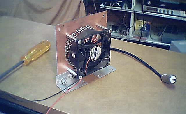
Work on the HV power supply is completed and I'm about ready to put the transmitter back together and heat 'er up. I got the idea to install a voltmeter on the front panel and I've glued that in place so will have to wait until the glue sets before I can proceed. In the meantime, I have a bunch of 2400-ohm 2-watt resistors that I might try and build up a dummy load with. According to my calculator, 48 of them paralleled would create a resistor of 50 ohms resistance rated at 96 watts; just about right. The trick will be to get them all close enough together so as not to be too inductive, yet far enough apart to cool efficiently. I have several muffin fans, one of which might be adaptable to cooling the resistors.
After that it'll be back to the modulator. BTW, I rechecked the power available from the audio amplifier you gave me and it easily puts out 150 watts into a 33-ohm resistor from the 70-volt tap on the output transformer, measured with a true-RMS voltmeter, but it's into clipping at that point. The clipping has a 60-cycle component to it so I'm thinking it's the unit's power supply bottoming out that's responsible for the clipping. The amplifier has lots of room for more filter capacitors if I ever need that power someday - perhaps when (if) I decide to upgrade to some kind of solid-state transmitter. In the meantime the modulator should work quite nicely with the 90-watt Globe. In rechecking the ratings on the final tube, I'm not sure it's doable at the 90-watt level though. I will be finding out soon.
Gotta start thinking about re-stacking my 50' vertical. I'm not very enthusiastic about that part of the project though, maybe because it has such a feel of been-there-done-that to it. My little tiller came with an edging tool, normally used to edge sidewalks and the like, and I'm thinking it would work as a trencher to plow in the coax out to the antenna. I'll give that a try one of these days.
Not sure I have enough coax. If not I'll see about using that 100-ohm balanced line you gave me. I'll have to scare up a couple of cores to wind some transformers on if I decide to go that route. You wouldn't happen to have a couple of twinax plugs (and associated jacks) you'd be willing to part with in your collection would you? I had some of those years ago but I've evidently tossed them out. No big deal, I'll get that signal - assuming I have one - out there somehow.
6/20
> have dug up the big paint bucket dummy load.
Thanks John. As I comment on my AM project I realize how much of it is stuff you've given me. All greatly appreciated!
> if you want to run it dry
> with 90 Watts I'll bet it will work fine
Yeah, I suspect you're right, especially since the 90 watts is DC input to the final; actual RF output will be something like 75 watts (or maybe 110 watts on AM). Anyway, I will try and not abuse it and get it back over to you as soon as I can.
> what kind of oil do they run in those things.
My guess it's transformer oil - the stuff they put in transformers, capacitors and the like. I could drill a hole in the transformer sitting out in our back yard and siphon out a gallon or two...
6/22
Ok, I put the Globe back together and fired it up.. literally..
It came up just fine in the standby mode: +300Vdc, -100Vdc, 6Vac all OK. When I threw on the HV I heard a loud ca-rack! and smoke poured out of the power supply. Even after the power was cut smoke continued to rise. I had to blow out the fire. I thought for awhile I was going to have to get a fire extinguisher.
What happened? As is often the case, it looked worse than it really was. A phenolic terminal strip had become conductive between two of the terminals, one carried the B+ output from the power supply, 750-800 volts with no load; the other terminal carried one side of the 120-Vac line. The loud crack came when those huge capacitors in the HV PS discharged across the gap. (I had connected the ground from one of the scope probes to the chassis which completed the circuit through the power line back to the negative terminal of the HV PS; the radio is not equipped with a 3-wire line cord, a deficiency I intend to correct.) Why hadn't the line fuse blown? I re-discovered that, oh yes, the fuse had been wrapped in aluminum foil; I had forgotten that little detail.
[We don't realize how much safer the electronic equipment of today is until we start to poke into and operate some of this old crap. With all those damned old TV sets of the 1950's in people's houses, it's a wonder we didn't burn the country down! Luckily, the technology was so unreliable the old stuff soon ended up in landfills. As electronics became more reliable, it became safer.]
Anyway, I checked out the circuits and nothing seemed to have been blown, other than the terminal strip. I replaced the 6-terminal job that burned up with two 3-terminal units and left an air gap between the terminals that had shorted out. I took a deep breath and turned it on again. This time, before turning on the HV, I brought up the grid drive and verified that the grid tuned up as expected. It did. I backed the drive control back down, took another deep breath and turned on the high voltage. No sparks this time. The front panel meter indicated 600 volts. Whew...
Now to get some kind of dummy load going and see if the final tunes up.
6/25
I tried out the antenna-in-a-can with one of the Syntor X [VHF] transmitters. Unfortunately, the SWR was very bad (25 watts forward, 24 watts reflected). I opened up the can and looked at the 50-ohm resistor in there. Yep, wirewound.. The Globe wouldn't tune up with it either. Rats.. Back to the 48 paralleled 2-watt resistor idea.
6/25
> hard to believe
> someone would go to all the trouble of building that
> can up so nice and then sticking a wirewound resistor
> in it. Oh well; it was worth a try.
> Why not just do the hundred Watt light bulb trick?
I could give it a try. I was looking for a load that would stay at 50 ohms. I measured a 100-watt bulb at about 9 ohms cold. I suppose it should get up to about 144 ohms at full brightness.
Anyway, I did the resistor thing: I mounted an SO-239 in the center of a 5" square piece of double-sided PC board, drilled a hole in a penny, soldered that to the center conductor of the connector, then arranged the 48 resistors radiating outward from the penny and soldered one end of each to the penny, the other to the PC board. It was a squeeze to get all the resistors on there, but I managed. I mounted a fan above the resistors. This worked well, but not perfectly. The Syntor could put 125 watts into that, with 15 watts reflected.
On to the Globe tune-up.
6/26
Ah, the joys of tuning up a class-C amplifier. Lessee, it's peak the grid and dip the plate; or was that dip the grid and peak the plate? Actually, that's one thing I do remember.
After considerable experimentation with different values of fixed capacitors paralleled with the tuning capacitors, I finally got a pretty sinewave at the output with a nice peak in the output power and a dip in the plate current. Measured with my scope on the output connector, the present combination of Ls and Cs in the tank produces 40 watts at the output with 54 watts (.09 A x 600 v) input, not as good as I had hoped. The actual impedance of the tube (as opposed to the hopeful 150 mA plate current value I had assumed) calculates to 3700 ohms. I re-measured the impedance of the tank with the tube in place and it hits dead on at the 2250-ohm value predicted by Bill Orr's chart. That's good, but it obviously does not match the actual tube operating in there. The trick is to get the input to the tank to look like the tube's output impedance when the controls are set for resonance. Since the Ls in the circuit are non-adjustable in this radio, there is only one combination of settings that produces resonance. A better match will require me to add some more turns to the tank coil. Gotta think about that. I may spring for a new tube before messing with that coil.
Whatever. I'll keep on tweaking. It doesn't take much to keep some people entertained.
This thing sure gets hot! I KNEW there was some reason transistors displaced tubes.
6/27
We went AM today, and I can see why those old transmitters weighed a ton. Continuous AM service is tough duty. After 30 minutes the HV transformer on the Globe was hot, the B+ had faded to 550 volts, and the modulator was almost as hot as the transmitter (although the modulation transformers remained cool). So I shut it all down before it melted. (It may not have melted, but I didn't want to find out.) No such respite would be given the transmitter at your local AM emporium.
AM lessons learned and re-learned.
With 1 kHz test tone, watching the scope:
- At full modulation the RF wave peaked at twice the CW level at about the same time the wave pinched off at the bottom.
- Full modulation required a peak audio output from the modulator about twice the DC input power to the final, around 100 watts.
- I tried the trapezoid linearity test. Best linearity is obtained with the transmitter set to about 35 watts output.
I put some nice spiky piano music on and listened on my portable radio:
- The radio sounds better if the RF output power is backed down a little. (See trapezoid test.)
- It's fairly easy to tell by ear when the transmitter is over-modulating.
- The plate current meter flickers slightly with the modulation. If this is excessive it's supposed to indicate some defect or other but I've forgotten what it is.
- A limiter/compressor is needed for the modulator. (I doubt I'll go to the trouble of equipping it with one though.)
- The modulator runs hotter than I expected.
- AM doesn't sound as good as FM
I found that about 40 volts of my lost plate B+ was being dropped across the modulation transformers so I took one out of the circuit. As expected, that decreased the input sensitivity of the modulator - no problem; I cranked up the modulator gain to compensate.
On to the antenna work. I gotta find my 100' tape-measure.
6/28
I found the tape measure - about the only progress I can report today.
While the adventure with the Globe transmitter has been an interesting trip down memory lane, and I intend to go ahead and put it on the air for awhile, it's real value has been as a learning experience. My thoughts are beginning to turn toward producing a solid state transmitter. What with power MOSFET devices being as cheap as they are, a couple hundred watts should be relatively easy to achieve using duty-cycle modulating techniques. The Globe experience has clarified some of the issues. As always, the biggest gain in these endeavors is in one's understanding.
6/29
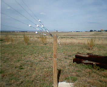
I staked out the locations for the guy anchors for my 50' LowFER-MedFER-AM-HF/spark-whatever vertical antenna. I decided to stack it in the same location as the 25-footer had been previously. Will have to acquire some posts and Sacrete one of these days and start hacking out the holes (shouldn't be too tough what with the ground being all rain-soaked). The ground is a tad more sloped than it was at the old in-town location. I may have to use longer posts on some of the corners. I want to try and use all the old hardware with as little modification as possible. My wish is that this be the last time I put this thing up. The next time it comes down, it falls down.
I decided not to pursue improvements on the Globe transmitter for now. I ran it for an hour continuously and it came through without melting, so I declared it air-worthy and set it aside to clear some space on the bench for a little breadboarding activity in pursuit of a solid state AM transmitter.
6/30
> A relatively high power FET AM carrier generator for
> your station sounds like an interesting and fun
> project,
Yeah, some thoughts on how to do it are going through my head. I've run across several web sites dedicated to ham 160-meter AM transmitters using pulse-width modulation. I should revisit those - no sense reinventing the wheel.
> I think the only real problem is the
> choice of running a class of amp such as "C" which
> generates a lot of heat but requires little or no
> filtering, or "D" or "E" which generates little heat
> but requires a lot of filtering.
I'm familiar with class-C but I've never been very clear about exactly how class-D, -E and the rest of the alphabet soup work. As you said, it should make for an interesting journey of discovery.
> But I know there are some hams who are running 500
> Watt CW HF power amps using just one $10 FET, using an
> on/off power supply trick.
Yeah, I'm sure you're right. Without having looked into it much, I'm guessing super efficiency (90%+) is probably not easily obtainable in a solid-state transmitter much beyond the 160-meter band. Not that it's a big deal. The overall advantages of solid state equipment far outweigh a little sacrifice in efficiency. Hams and users of land mobile radios have long since decided on broadband amplifiers - such as those used in the SyntorX and many others - requiring little or no tune-up. Broadcasters still want efficiency in order to hold down the electric bill. Tubes still hold the edge in FM broadcasting at the higher power levels, I think. Tubes own the television broadcasting, radar, satellite up-link and microwave oven bidnesses.
> I hope you decide to use some of the
> ideas incorporated into the shorter one we put up, and
> that you will use the big loading coil, especially if
> you kick things into lowfer mode.
My calculator tells me the radiation resistance of a '50 vertical with a good conventional ground should run in the neighborhood of 1 ohm at 1710 kHz, maybe as high as 2 ohms using an elevated counterpoise, a thousand times that of the same antenna at 175 kHz. At a given Q, the loading coil at 1710 kHz will be smaller by a factor of 100 than a 175 kHz unit. The coil will not be required to have a super-high Q (say >100) to operate at reasonable efficiency. In fact, super-high Q might be a disadvantage in AM mode, wiping off those hard-won sidebands.
7/2
I've been snooping around the internet again, seeing what I can dig up on solid state class-e AM transmitters. The exercise is a bit sobering. There is plenty of information out there and solid-state transmitters are very much do-able, but it's all homebrew and I'm now less convinced I want to go down that road. To be fair, the designs I've seen from the class-e folks are pushing the envelope; the drive is on for operation on ever higher frequencies: 75-80 meters, even 40 meters. 160 meters is easier, but I'd be looking at paralleled MOSFETs, massive heatsinks, custom wound transformers and other inductors, and large filter components. Re-doing some old Viking or something still seems the shortest, if not the most electrically efficient, route to medium-wave. Not that I've given up on solid state; I haven't. The class-e approach appeals to the engineer in me, but I don't know if I have the energy (or cash) for the effort such a project would require. Will continue researching.
One concept firmed up in my mind as a result of my poking around, applicable to both tube and solid-state designs, is the idea of negative peak limiting. It's another way of defining what I've heard called 'super-modulation'. Basically what that does is rectify the negative audio peak just before it would cause the carrier to pinch off, stores the energy in a capacitor and makes it available to the PS for the next positive peak. It's done with a handful of diodes on a transmitter employing a modulation transformer, and in one of the audio stages on a solid-state class-e transmitter. It allows the application of more power from the modulator than would otherwise be allowed without causing over-modulation distortion. [Ordinarily, the RMS power limit from the modulator is 1/2 the DC input power.] A 100-watt transmitter might sound like a 150-watt transmitter (wow, a whole 2 dB improvement!). I'm not sure what the practical limit is. Could my 50-watt Globe sound like a 150-watt Globe? Could a 100-watter sound like a 1000-watter? The limit is probably determined at the receive end. Supermod might screw up the AGC on some radios, causing distortion. In this country, FCC rules prevent legit AM broadcast stations from employing super-modulation, although I understand it's legal in Mexico. It's also legal for hams.
7/2
> The power supply, which amounted to the modulating
> device, was the tricky part. Seems like it was in
> either "QST" or "73."
Yeah, I think virtually any amplifier can be modulated using that technique. Pulse width modulation is usually done at something like 100 kHz using a separate switcher. What I was hoping to do is have the switching transistors in the final also do the modulation - in other words have the final operate in pulse width-modulated mode. The problem with that is the transistors available are not fast enough for PWM directly at the carrier frequency. I was thinking perhaps 'pulse density modulation' might work. The finals would be supplied with full-width pulses at the carrier frequency but their density would vary with the modulating audio signal. A delta-sigma modulator could supply that sort of thing.
> It sounds like you don't think your AM station has
> enough juice to be meaningful.
> It might surprise you.
Given a clear frequency and a receiver located away from man-made noise sources, you could very well be right. Gonna invest in some posts and concrete tomorrow and get that antenna project underway. Also need some more of those 6 kV diodes so's I can SUPERmod my little blowtorch. I'll melt that tube yet!
7/4
I spent last night under the stars in our backyard. I got a beautiful sunset, the stars, and a little AM Dxing with the old GE portable away from the usual QRM. I had almost forgotten how much better an AM radio can work when it's free of the noise produced by all the electrical junk in our lives. That fact has to be part of the reason all those little 250-watt stations of the '20s and '30s were so widely heard. I checked 1710 kHz: ahh.. nice and quiet.
I started on the antenna project this morning and have managed to punch one post hole about 2' down. The easy dirt, damp from rains this spring, runs out at the 1-foot level and it's the usual dry gravelly clay below that. I have 8' posts, so will dig the holes 3', leaving 5' sticking up (duh).
AM research:
Two items;
I learned what could be causing the modulation amp to get so hot when driving the modulation transformer connected to the Globe transmitter: Since the secondary is carrying the plate current for the final in the radio, the iron in the transformer becomes polarized. This could present an unbalanced load to the modulator, wherein the impedance is lower on one half of the audio cycle than it is on the other, causing one side of the push-pull final (assuming it is push-pull) to draw excessive current. If the core is saturating, the current could be really excessive. I don't know if that's what's happening or if the amp just normally gets that warm under load.
Regardless, I've found a fix, and a better way of doing things generally. It's called 'modified Heising' modulation and, instead of the secondary of the modulation transformer carrying the final current, the current is carried by a heavy choke - something like 40 Hy - in series with the plate B+. The audio power is coupled from the secondary of the modulation transformer through a capacitor - around 3 uF - to the plate of the final (actually to the RF choke that feeds the plate). The capacitor prevents DC from flowing in the transformer secondary, and thus eliminates the related problem of core saturation. Voila! I just happen to have a 3 uF 2000 volt capacitor (I've had that thing for 40+ years!). Now all I need is a big choke. And those things are scarce as hen's teeth (the AMers must have bought 'em all up). I do have a couple of 24-volt battery chargers in the shed that might yield such a choke if I were to look in there.
Another path in the pursuit of truth has produced interesting data. While poking around the International Rectifier web site, I discovered what IR calls 'low charge' MOSFETs. These are versions of their Hexfet line that have reduced gate charging times. I never figured out what compromises are made in the specs on the transistors to accommodate that capability, but I did notice the LC units are not available with an extremely low ON resistance spec, as are some of the non-LC units. Anyway, the reduced gate charging times should allow the transistors to operate efficiently as switchers up into the low MHz range.
I'm looking at the IRF740LC, good for 10 amps with an ON resistance of .55 ohms. 100 volts at 10 amps might produce a kilowatt. (The transistor, when mounted on a suitable heatsink, is good for 125 watts dissipation.) Two transistors operating in push-pull is probably more realistic for a kilowatt. 200-300 watts is probably even more realistic (if it works at all).
[BTW, power MOSFETs achieve high efficiencies only when operated as switchers. A 'normal' tuned-gate RF amplifier is a much less efficient beast, with numbers similar to those typically achieved with, ah... tubes.]
7/5
Ha! Where there's a will there's a way. I found a 53-Hy choke in the form of the output transformer from a 20-Hz ring-voltage generator, one of the pieces of junk I had forgotten even having in our storage room. I don't remember acquiring that thing. The nice thing about this particular piece of iron is that it combines high inductance with low DC resistance. Now, as soon as I can get some more HV diodes in, it's on to equipping the Globe with a modified Heising super-modulator!
Work continues, slowly, on the antenna project.
7/13
Three posts are set for my 50' vertical antenna. Progress is slow.
Inside efforts include the building of a new interface between my Globe transmitter and its modulator (the PA amp). I'm using lots of heavy iron, [including the recently discovered 53 Hy choke] in the construction of that thing. I love heavy iron.
7/15
I completed work on the modified Heising modulator and it works as expected. The negative peak limiter works also, but not exactly as I had expected. I was expecting the circuit to work as a clamper that establishes a DC reference a few volts above zero on the plate and adds the modulating waveform on top of that. Wrong! The circuit actually operates by simply lopping off the negative peaks below the reference. OK, the transmitter never over-modulates, but the transmitted audio waveform is distorted if the transmitter is driven hard by the modulator. In other words, it's not the super-modulator I had expected. That will have to wait until I can perfect a pulse-width (or more likely, pulse-density) circuit.
7/17
> How's the heavy iron coming?
The new modulator circuit is completed and it looks a bit like something from a high school physics lab. 'taint safe either. Lethal voltages are right out there for god and everybody to get into.
> And the final post hole?
As soon as the coffee is done, and I hit the send button on this, I'll be out there planting the last post. Too hot to do it any time of day except early morning. It hit 101 yesterday.
7/18
> Let me know how the antenna is going.
I have all four posts set, finally. The last one was a 10-footer, needed to equalize the slope of the land somewhat so as to keep the guy lines equal in length. [It looks] a little out of place among the shorter ones in the guying system.
7/20
Progress on the transmitting antenna is slow. I decided to add some risers to a couple of the posts.
7/22
The guy anchors are completed for the antenna here. One of these mornings I'll be trotting out the antenna and get it all lashed up and ready to jack up. It's been a tad windy the last couple of mornings, causing me to postpone the event. This morning would have been perfect had I been ready.
I've divided my time lately between playing with circuits on the bench and surfing the internet in search of the optimal circuit for a class-e AM transmitter. I've found some interesting stuff. One of the clearest and most helpful articles I've found I had actually read before, some 15 years ago in the Western Update, by none other than my genius friend Mark Mallory. He describes a simple MOSFET LowFER final that achieves an astounding 98% efficiency. Here's the reference if you'd care to glance at it.
I see no reason that circuit wouldn't work just as well at 1710 kHz.
7/23
> Just be prepared to put a lot of filtration on the
> output to suppress harmonics.
You're right. My thought was to wind the primary of a transformer with the required class-e inductance and then series resonate the secondary to the operating frequency with a coupling capacitor out to the load. This would also accomplish the required impedance transformation to 50 ohms (the number of turns on the secondary would be dependent on the needed impedance transformation; the coupling capacitor value would be selected for resonance at the operating frequency). Another benefit of a transformer is that it would allow an easy conversion to push-pull, with it's resultant suppression of the second harmonic.As usual, I don't have the right core on hand. Amidon will get some more of my money.
> This won't be a high Q
> narrow band antenna running 10 Hertz modulation
> bandwidth.
Right again. After all those years thinking about Qs in excess of 100, gotta get used thinking about Qs around 10.
> MOSFETs are very efficient at lower freqs if you have
> the drivers to turn them on and off quickly enough.
Yeah, I tried (at 1710 kHz) the old 2N2222/2N2907 driver pair into the gate of the final of my LowFER transmitter. It showed good rise time on the scope with that particular MOSFET. I haven't tried the new IRF740LC in the lash-up yet.
With Toby's help, I hauled the old antenna out of the barn yesterday. I don't remember it being so heavy that it required two people to carry(?). Another sign I'm getting old I guess. The guys and insulators are a tangled mess. It's gonna take some time to get that all straightened out.
7/24
> the rule of thumb for power FETs
> is that the more power they handle the more input
> capacitance they have, so the more drive they need to
> switch them fast.
Yeah, that's probably correct. It seems pretty reasonable anyway.
From my reading of the class-e folks, I get the impression they're sort of wedded to MOSFETs. Their push seems to be to get them to work at ever higher frequencies - paralleling half-dozen transistors on massive heatsinks, driving them with large amounts of power and modulating them with separate class-d amplifiers. At some point, as you point out, one probably should give up on MOSFETs (at least the present state of the art anyway) and shift to bipolars. From the literature I've read, class-e principles are useful right up into the microwave region of the spectrum.
[I'm still a little amazed that NIST, in their wisdom, chose to upgrade the transmitters at WWVB with tube units - albeit old second-hand ones. Maybe they're running those things class-e. There is no reason they couldn't.]
OK, back out to untangle guy lines. I got so carried away with it yesterday I stayed out a bit too long and got borderline sunburned. I shouldn't do that. It only gives more business to my dermatologist.
7/25
> Seems to me that there is a cute trick to getting
> class E opperation at high freqs. I think they use a
> power supply with a quarter wave or a half wave length
> of interconnect wire to the drain of the FET (I forget
> exactly which works, 1/4 or 1/2 wave)
Probably some weird fraction of a wavelength. A transmission line tank works just like an LC one. The key to class-e operation is to tune the tank to 1.2915 times the operating frequency (where the hell that particular number comes from I haven't figured out yet) so the transmission line tank for class-e would be something like 1/5th the wavelength of the operating frequency.
> even though the FET gate is being driven with a
> sine wave.
Yeah, sinewave drive is the only practical way to drive a MOSFET above about 2 MHz. 'course that requires lots of drive power and eliminates modulation capability in the final - the modulator must be a separate deal, just as it is for class-c plate modulation. The class-e ham enthusiasts might want to be thinking bipolar for their higher frequency transmitters - class-e bipolar.
7/25
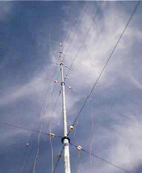
What a mess! My 50' vertical that is. I've spent 5-6 hours so far just sorting out the guy wires. Considering that the antenna has 20 guys - 5 levels with 4 wires at each level - plus the tophat skirt wires, plus 4 down-wires, plus the four temporary 'helper' guys on the lowest level (to help keep it from tipping over when I'm up there on a ladder jacking it all up), it's no wonder it's tangled like a fisherman's nightmare. The antenna is at least vertical now, if not yet on its pedestal, held in place by the lowest set of guys. There is still considerable untangling to be done. After the wires are straightened out I'll add the lowest length of pipe to the unit and hoist it onto its base before jacking it up to full height. I'm thinking of adding a 5' non-guyed extender to the top just to gild the lily a little. [A 10% addition to the antenna's height should increase the radiation resistance by about a third.]
7/27
OK, the mast is on the pedestal and plumbed. The first level guys have been tightened and reinforced with their helpers. The ladder has been lashed to the mast. About all that's left is to clamp up the gin pole - probably do that this evening if there's no lightning in the area. The antenna should then be ready to telescope into place - probably do that first thing in the morning if the wind isn't blowing.
The process takes about 2 hours and is a bit scary. One of the drawbacks to doing antenna work early in the morning is that no one in my family is around to be my ground person. Not that I need any help, but it would be nice to have someone to haul me to the hospital if I should fall.
My erection probably will have taken place by the time I report again.
7/28
Well I got the darn thing up (antenna, that is)..
Hard work.. I was so sore from yesterday's activity I almost didn't start this morning, but went ahead anyway. Hope I don't have to do it again soon.
After I recover from today's effort I'll spend some more time tweaking up the guy tensions then start on the grounding system. I opted not to use an elevated and insulated counterpoise - people don't like getting strangled by my wires - so will try for a full quarter-wave radial system laid on, or just below, ground level. My thought was to trench in the radials an inch below the surface. It's going to require a fair amount of wire - quarter wave at 1710 kHz is about 142'. The 2500' insulated spool you gave me would do about 17 radials. Half a mile of trenching is a lot. I'm hoping my Mantis tiller, equipped with its edging tool, will dig the trenches. Maybe I can dream up some kind of rig with a wheel to roll the wire into the trenches.
7/31
> If I were you I'd just try repairing the lowfer ground
> counterpoise and hook that up before I went to any
> great trouble with underground radials.
Yeah, I'll give that a try. There isn't much left of the old counterpoise from the LowFER antenna we put up a couple of years ago but I'll hook up what's left.
> After all, you aren't trying to squeese that
> last half a dB out of a 50,000 Watt station.
I'm trying to squeeze out the last half dB out of a 50 watt station.
> Hope you feel better after the big antenna raising.
I'll live. Still got some work to do getting it plumbed. It's got a decided tilt to the west that isn't noticeable up close but is very evident from 1/4 mile away.
7/31
> Once the radials are on or under the ground you are
> not really talking about resonant length anyway.
Yeah, I think that's generally correct. What I read speaks of the radials needing to be MINimally 1/4 wave in length. The idea is to get the ground currents to flow in the radials rather than the earth. Constructing an insulated counterpoise and then tuning it to resonance is the 'other' approach. The idea there also being to avoid pushing current through the earth. Practical - less than perfect - systems probably incorporate elements of both approaches since it's not possible to completely shield the earth from the near field, especially beyond a less-than-1/4 wavelength counterpoise. There's a fairly good discussion of it in ARRL's antenna book - in the section about low frequency verticals.
Anyway, you got me to thinking and now that I think about it, 141' radials probably would not be worth the effort. Better to have maybe 32 or 64 50' radials rather than 16 141-footers. I can still utilize the long fences, the well and other grounds around here to supplement the radials. 'course, once the wavefront is launched - out beyond the near field - groundwave propagation necessarily induces ground currents, and the lower the resistance of the soil the better the propagation.
> I'll bet it's
> broad banded enough to work on the AM band with no
> problem.
Coil losses should be drastically reduced at 1710 kHz compared to 175 kHz, making ground losses a relatively larger factor. Then, on the other hand, radiation resistance should be much greater, although still pretty small (since the antenna is still quite short relative to its operating wavelength) compared to ground losses.
8/12
The antenna project has stopped for now. Gotta install some anchors to stiffen up my posts/guy anchors. Stiffening the posts allows a better tightening of the guys (giving me the ability to tighten one guy without causing the others sharing the same anchor to loosen). It means digging more holes to be filled with concrete.
8/24
This morning I started on the short guys that will stiffen the guy anchor posts on my 50' - actually 56' now - vertical. So far I've only started poking the holes into the ground, and, like before, the ground is so hard it'll take awhile to get that part done. By then I might have a few bucks in my pocket and can spring for a couple more sacks of 'crete.
I want to order up some cores to use in constructing a transmitter. Still not sure if the variable pulse density technique can be used to modulate a class-e final directly. [The class-e people currently use a separate modulator - class-d or something - to do the job.] If it works I'll write it up.
8/31
This morning I cemented in the auxiliary anchors that will help stiffen up the guy anchor posts for my vertical antenna. Hard work. I'm putting stiffeners on only three of the anchors
even though the fourth one is longer than the others by 2 feet. That fourth post is much thicker and heavier (must be close to 200 pounds) and I don't think it's going to be bending much.
Anyway, after the concrete cures for a couple of days I'll finish up the antenna and start on the counterpoise and the feedline from the shop. Then it's on to some kind of loading coil, the firing of the transmitter into the antenna, and the debut of The Mighty 50-Watt Clear-Channel Voice of Tex-Mex (or whatever).
9/17
Work on the vertical proceeds, and I've begun building what I hope will someday be a solid-state AM broadcast transmitter.
9/30
I completed work on the transmitting antenna about a week ago but didn't get around to tuning it until Sunday. Using the roller inductor you gave me several years ago and a variable capacitor from an old AM receiver,
the antenna tuned up like a dream. I was expecting it to act like a LowFER, all fussy and touchy. No such thing; tuning was nice and broad and well behaved.
Judging by the voltage rise at the base of the antenna compared to the voltage from the 50-ohm signal generator I was using as a source, reactive impedance on the antenna and ground system appears to be about 800 ohms at the 1710 kHz operating frequency.
[Some unknown fraction of that is, of course, non-reactive: radiation resistance plus ground resistance and other losses. The charts I've seen suggest a 56' vertical should have a radiation resistance of around 2 ohms at 1710 kHz, but that's for a thin wire. This stick is 'fat', with a tophat and 4 vertical wires; radiation resistance could be considerably greater. (Capacitance measured about 600 pF, typical of a full quarter-wave vertical at 1710.) Only about a third of the roller inductor's length was needed to achieve resonance; so losses in that should be minuscule. The rest of the losses are, of course, from ground resistance. I haven't figured out a way of measuring either radiation or ground resistance but assuming 2 ohms Rrad and ground losses 10 times higher, efficiency comes in at only around 5-10% - really bad for a commercial AM installation, but 1000 times (10,000 times?) better than any LowFER I've ever heard of. Two or three of the 35 watts from the transmitter might actually get out the door.]
I used the signal generator, set for 1 volt (pp), to get a couple of milliwatts into the antenna and checked the 1710 spot on the dial using the receiver in the house.. Dead quiet; the S-meter read 50 dB over S9. I carried a portable down to the end of our driveway (near the power line) and, while it wasn't fully quite down there, I was still getting a respectable sig.
This morning (Monday) I took a deep breath, hooked up and fired up the Globe...
Which didn't seem at all stressed by the experience. The tuning controls acted exactly the same as they do on the dummy load. The receiver's S-meter pegged.
So... it was on to some modulation: 1 kHz@0 VU=100% - so far so good. Will put on some music tonight and go off on a little DXing expedition. Fun stuff!
Update: This morning (Tues.), finding myself wide awake at 2 AM, I put on the transmitter playing German beer drinking music - in celebration of it being almost October - and went for a ride in the family car. Got about 10 miles out before gas ran low. I could still hear the station just fine, noise-free when I shut off the car.
[It's the result I had hoped for. As we know, nighttime propagation makes the top end of the AM band, with its thousands of locals, almost useless for anything other than.. well.. local reception. But 1710 kHz is cheating - it's an out-of-band clear channel with no stations assigned, yet receivable on most AM radios made in the last 10 years. It's virgin territory.]
When I got back the Globe was so hot I couldn't keep my hand on the case (will have to provide it with a fan if I keep this up). The modulation amp was moderately warm; the modulator iron was stone cold.
AM is a different animal.
10/14
I have a prototype solid state transmitter spread out on the bench here, along with three of the 12-volt batteries you gave me. Gives me three voltages, 12.6, 25.2 and 37.8 volts to play with. I can make changes and test them at 12 volts before committing to the higher voltages. I have yet to smoke one of the finals, although I did manage to blow the 10-amp fuse in my multimeter.
Anyway, the transmitter is up to 160 watts - pulls about 5 amps at 38 volts, 80-some percent efficient. Seems like I should be able to get that efficiency up a little. The drains of the finals have about 125 volts peak on them. The audio from the modulator will double that, to around 250 volts - approaching the 400-volt rating of the finals - so maybe I'd better call this design a done deal and actually build a working transmitter.
I melted my dummy load with that 160 watts! I forgot to plug in the cooling fan and, before I figured that out and got things shut down, melted solder was dripping out. Fortunately the resistors were not harmed and I was able to get them all soldered back in. Measured 50 ohms. I'll be leaving that fan on all the time from now on.
10/15
> Radio Heaven!
Yeah, I'm having fun with this thing [solid-state AM xmtr]. After lots of fiddling and tweaking I've gotten the efficiency up to about 93%: heatsink on the finals warmish, dummy load hot!
10/20
Still fooling with the AM transmitter up here, trying to work up an output filter. The finals stay nice and cool when powering the dummy directly, but run warmer when pushing power through the various filters I've concocted. The filters themselves get pretty warm too.
I keep getting RF burns. Not used to working with all this power.
10/24
I spent a good deal of the week trying to work up a reflectometer for use at 1.71 MHz on my AM xmtrs and the 56' vertical. (I don't have a slug for the Bird for that frequency and the SWR meter part of the little Radio Shack unit you gave me doesn't seem to work, although the power meter does, sort of.) So, instead of being outdoors soaking up the remaining few days of fall, here I was scratching my head over why the 1-volt (pp) AC sinewave coming out of my homemade directional coupler would not rectify out through a diode to something like half a volt DC and drive a 200 uA analog meter movement. I got exactly 0 volts out of the diode and precisely zero deflection of the meter (???).
After substituting several diodes, including germanium, silicon and Schottky types with no success, I was beginning to think I really didn't know how a diode works! Well [blush], it turned out I was simply misreading the scope. I didn't have a 1-volt signal, I had a 1/10 volt signal. There was no way this would forward-bias a diode and deliver 200 uA. Sooo, I gave up on the analog meter and brought the rectified DC out to pin jacks for reading on a high-impedance digital multimeter. It's a tad clumsy, but works well.
Anyway, that windy day I was trying out the (finally) perfected reflectometer on my vertical antenna. The antenna tuned up OK with the meter but the system acted flaky, with the reflected readings bouncing around and the tuning capacitors in the Globe arcing. It was fairly obvious the wind was causing this - first darn windy day of the fall, almost, and it was screwing up my antenna. This morning I clamped the lower ends of the 4 vertical wires on the antenna to the central pipe and tried again...
Success. If I can believe the readings I'm getting - which I probably shouldn't since diodes are non-linear at low voltages, though the Schottky rectifier I ended up using should be better than most - the VSWR, after adjustment, works out to something like 1.07:1. 200 watts into the antenna should reflect less than a watt.
Nothing much else to report on the radio front. I had started construction of the 200-watt solid state transmitter before I got hung up on the reflectometer. Will now get back to that.
10/30
After drilling and sawing and filing all week I have the 42 volt/5-amp power supply for the unit pretty much completed. I'm using parts for this transmitter that have been cluttering up my life for 30-some years. I scrounged the power transformer, as I recall, from some old equipment when I was in the military in the 1960s. That darn thing was literally under my feet on the floor in my shop in the basement of the little house in town for 20 of those years before being banished to the barn when we moved out here. The ripple coming out of the constructed supply is about 300 mV (pp). Not too bad, 48 dB or so below peak modulation, if I'm figuring correctly. I'd like to get it down a little more but I threw away most of my big capacitors when we moved, so will have to live with it. I can't tell if this power supply will hold up under continuous operation until I get the transmitter completed. The resistor I'm using to test the supply is rated at 'only' 100 watts and it threatens to melt long before the power supply does.
Will now move on to installation of the transmitter components in the case. Nearly 75% of the volume on the completed unit will be the power supply, with the transmitter itself sort of over in the corner like an afterthought.
11/2
Transmitter report:
Thing's hotter'n a pistol. I reread Mallory's article and built yet another output filter for the unit - the right one this time - and the efficiency of the final shot to 98-99%. Rounding errors are becoming troublesome when doing the calculations. If I don't use all of the digits shown on the meters (current, voltage), I sometimes end up with an efficiency calculated to be greater than 100%! The heatsink on the finals are stone cold; the drivers get warmer than the finals. Also, the output voltage of the power supply, as constructed, ended up being 42 volts (at 5 amps) for 210 watts. At 98% efficiency, I'm getting all of that 200 watts RF out I was shooting for. The extra efficiency and higher PS voltage put the receiver-type variable capacitor I was using to tune the final over the edge I guess. The higher output power causes it to arc over, so I had to substitute one of the transmitting types you gave me for the testing - they don't call 'em 'transmitting' capacitors for nothing. The as-built unit will use a fixed-value capacitor in that location if I can scrounge one that will handle the voltage and current.
The RF burns are getting serious-er. I just got a nasty one after substituting that capacitor and before realizing the shaft is not insulated! The guts of the transmitter are still spread out on the bench to make experimenting easier. Gotta get this thing packaged up.
11/5
OK [blush], I guess I was a little optimistic there on the transmitter efficiency. Seems my ammeter was lying to me. After substituting another digital meter and calibrating the analog panel ammeter correctly, efficiency now calculates out to the low 90s. The actual result depends somewhat on planet alignments, phases of the moon, etc...
Which is to say, this amp doesn't tune up like yer typical pi-network-matched class-c final. It will drive about any load you care to hang on it, but the reactive component must be tuned out. The filter recommended by Mark Mallory is a simple series-tuned LC network. At resonance, the network "disappears" and the final sees the load impedance. It works like a champ: When the output network is correctly tuned, the signal on the load is a nice clean sinewave and E divided by I on the meters calculates to exactly the value for R the formulas say it should.
The trouble is getting the thing tuned up without a scope (or spectrum analyzer). Simply tuning for maximum forward power on my directional coupler/detector doesn't work because the detector on that thing indicates only peak power; it gives no indication of the purity of the output signal. Unlike a pi network-tuned output stage in which maximum energy transfer occurs at the point of maximum purity of the output signal, the class-e final doesn't seem to work that way. Many combinations of E and I will cause a maximum in the output power, but only one - at the calculated value for R - results in maximum purity in the output signal. One tunes the final not for a peak or dip, but for a particular value of E and I.
Deep doo-doo.
I can't leave the transmitter on at 200 watts into my dummy load for more than a minute or two. Even with the cooling fan running the resistors quickly overheat. (Those things take a licking and keep on ticking.) So I've been using the antenna as my dummy load (does that make sense?). When the weather is soggy like it has been lately, however, something out there arcs, so gotta wait until broad daylight and everything dries off. At 200 watts the antenna's 800-ohm impedance implies 400 volts RMS on there when the transmitter is radiating.
11/6
I was thinking of writing up an article on the transmitter and hoped there was some way to tune it without equipment, using only the panel meters. The guys with the comments and guidance on the class-e forum and the "official" class-e web site highly recommend at least a 50 MHz scope for messing with class-e, so it's probably no big deal, but it might leave out some folks. Now that I think of it, anyone tackling the construction of a 200-watt transmitter will no doubt have the necessary equipment.
11/17
Progress toward boxing up the broadcast transmitter is being made. I decided to brew up a dedicated carrier generator/exciter to include in the unit - make it a plug and play deal so to speak.
I also concocted an interesting application for the AD835 multiplier chip - as part of a forward/reflected power meter in the AM transmitter. It samples RF voltage and RF current and multiplies the two. E x I... voila! Watts..
11/17
> It sounds like you're doing a very nice job on the
> solid state AM xmitter.
Dunno about that. I'm sort of stuffing things into the case wherever they seem to fit, at a rate of about one part per day. It does seem to be coming together in a fairly respectable-looking unit though.
> I'm curious to see what modern technology looks like
> when applied to good old AM.
Don't know how modern it is. Class-e has been around for awhile and the pulse-density modulation scheme I dreamed up didn't work. (The pulse-density modulation circuitry worked but the final didn't like it. Instead of the output being amplitude modulated, the output signal would just break up into garbage at any setting other than full power. It would have required impractical amounts of filtering at the amplifier output to clean up the signal.) The pulse-density idea might be applicable to some future class-d (or something) modulation amp, but then again I'm not into audio amps just now. Maybe when I scale this thing up to a couple of kilowatts... The modulator for the unit is your good ol' public address amp.
> I'd like to see anything you've written up about it.
I've been pecking on an article about the project for awhile and will send it along when I iron it out a little more.
11/23
I glanced a little at Clint Turner's MedFER pages and PSK-31 (or whatever it's called). The idea popped into my head that after I get over the novelty of transmitting music in AM mode, the 200-watt transmitter would work just fine for PSK-31. Hm.. Something else to think about.
1/3
My AM efforts have finally jelled in a working 200-watt transmitter. Had I known the thing would be the hassle it's been I may not have started the project. Actually, now that I think of it, I remember mentioning, back when I first got interested, that building a solid-state transmitter from scratch would be a hassle. But, as they say, it's not the destination but the journey...
The wind affects my vertical more than I like. It's those down-wires; I need to guy them somehow so they don't move so much in the wind. The ammeter on the transmitter moves in step with the wind. That movement may have affected my LowFER BPSK results back in the days when I was trying to perfect that mode. It's a factor I never gave much consideration to.
1/4
One sixty meters, eh.
> Yep, they run power, big vertical arrays, and shut the> thing down the first day of Spring
Sort of like broadcast stations talking to one another. I've noticed that 75-80 meter nets have a fairly modest geographical spread. The same, only more restricted, would be the case on 160 meters I suppose. The fact that it's out of the ordinary and a little difficult appeals to me somewhat. I would think PSK31 or some of the other narrowband digital modes would appeal to those guys. Maybe not.
> believe when you were scratching your head over the
> old Globe xmitter you mentioned that you thought it
> would be easier just to build a solid state one from
> scratch.
I'm sure you're correct. Working on that darned old Globe transmitter, and to a little lesser extent, the solid-state job, has been some of the most enjoyable time I've ever spent.
As for the solid-state transmitter, after perfecting the circuit, canning it all up into a working unit was done in slow motion. I'd come out here and install something, then contemplate where the next part would go until, racked with indecision, I would give up for the day. The following day, after ruminating for 24 hours, I'd install something else. Sort of like a chess game - I was trying to think ahead so as to end up with a rationally laid out transmitter. I succeeded fairly well.
Another problem was the destruction of CMOS ICs on the exciter board while trying to get it up and running. I'm not used to all that RF bouncing around all over the place! After grounding, shielding, more grounding and more shielding, I managed to tame that tiger and ended up with a pretty effective tune-up procedure in the process. The transmitter can be tuned using only a multimeter, although it's nice to have a scope to verify waveforms. Scopes have problems too, however, related to grounding. Pickup from the probe grounding leads can lead to misinterpretation of what's presented on the scope. Oh well. We learn.
1/18
I have about $30 out of pocket invested in my AM transmitter so far, but I've run into a snag that might cost me some more bucks. It's the output tuning capacitor. I'm finding that the ones I've tried in the completed unit don't stand up. They either arc over, in the case of the air variables, or heat excessively in the case of the fixed mica units I've tried, eventually shorting and taking out one or both of the final transistors. In my bench tests I used the big old air variable unit you gave me. It worked just fine, but I didn't leave enough room in the transmitter for it. A solution has presented itself in the form of a Jennings vacuum variable on eBay, the smallest unit Jennings sells actually. It would just barely fit in there if I'm measuring right. The guy is asking $40 minimum with no bids so far. One surplus outfit sells the same unit for $95. New they're around $200. Jeez, I hadn't expected to be spending any more substantial money on the transmitter, but looks like I may have to dig a bit deeper.
1/24
> What voltage appears across the capacitive reactance
> you've got there when you run 200 watts?
Hm... 200 watts is 2 amps at the output connector and 2 amps through the output series network. The reactance of the capacitor is 250 ohms, therefore, by ohms law, 2 x 250 = 500 vRMS or 1414 volts peak to peak. With modulation, the voltage doubles to 2828 volts peak to peak.
1/25
I finally resolved the capacitor breakdown problem in the solid-state AM transmitter - without spending any money, it turned out - by series paralleling the right combination of mica caps (from the collection you gave me) and placing those in series with a 1100 pF receiver type air variable I've had around since at least the early '60s.
I spent yesterday rearranging the innards of the xmtr and installing the new stuff. This morning I've been running it, along with the modulator, into my homemade dummy load. Had to fortify the dummy a little so it would stand up under continuous operation. I moved the fan 1/8" closer to the resistors, and drilled some holes behind the resistors to improve air flow. Seems to have worked because not only has it not melted (although it gets pretty hot and smells funny), it stays within a few tenths of 50 ohms from a cold start to hot.
I'm sitting here listening to the transmitter playing through a portable receiver and it sounds, well, like AM does. Cutting the bass and boosting the treble through the console improves the sound considerably. There's a tad bit of residual FM from the synthesized exciter, but it's only noticeable when there's no AM modulation and the volume on the receiver is turned up.
If the wind's not blowing tomorrow morning I'll probably load up the antenna and do some radiating! The transmitter and antenna are tuned for 1710 kHz but the system slips effortlessly down to 1700 with the removal of a single jumper. Don't know why I'd ever do that but you never know - maybe during some kind of emergency that knocks the local legit guy off the air. The nearest station on 1700 is in Des Moines, at least that's what I hear when I listen on the channel.
1/28
> You've been very busy, and I
> like the way you build.
The way I've built this thing is SLOW. My tolerance for sore butt, eyestrain and other hazards of bench work seems to be falling as I age. The cold room, the computer and the call of the recliner in front of the TV set tends to further shorten the daily time on the project.
> you can actually put a lid on your
> xmitter. I'll have to work on that part.
Yeah, I tend to start with boxes smaller than they really should be and end up trying to stuff it all in (sort of like getting my rear end into my pants lately).
2/16
I added a big capacitor to the modulator's power supply in hopes it would stiffen that up some, improve low frequency response and on-air sound of the AM rig. I also dreamed up a negative peak clamper circuit consisting of a fast diode tied to a separate 2-volt power supply for the modulator. The idea is that whenever the modulation signal, which rides on the power supply B+, drops below 2 volts during negative audio peaks the diode conducts and prevents the final from pinching off. The current drawn from the 2-volt supply is forced back into the transmitter's 42-volt supply and presumably is available for the next positive peak, providing a form of super-modulation.
Well, I never got very far in testing that lashup. Everything worked fine with a test tone: freq response about 70Hz-10kHz, negative clamper good, 100% modulation easily achieved. Then I tried some music.. Fifteen seconds into that.. BOOM, one or both of the finals shorted, taking out the B+ fuse. Shows the power of music, I guess. Anyway, the AMer is dead in the water again and this time I'm fresh out of transistors. More money to Digikey. Think I'll go with a little higher current FET next time, duh.. and maybe some transorbs. Not right away though. Gonna walk away from the project for a month or two....
Today
The IRF740LC finals have been replaced with IRFP350LC (16-amp) units and transorbs added to the modulation input. The class-e output stage and the output filter components - including that big variable capacitor - have been moved to a separate cabinet, with the power supply occupying the original cabinet. The 200-watt 1710 kHz class-e AM transmitter is a done deal. The tube-type 35-watter is now the station backup.
