|
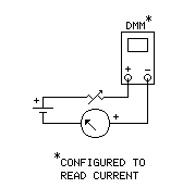
Wind Speed Anemometer InterfaceVoltage-to-Current ConverterDrives distant analog meter, digital meter, computer interface, data logger, etc, singly or in tandem. Built-in zero offset. Max Carter The 1733 Anemometer from Adafruit is a reasonably-priced, well-built wind-speed sensor. It features a built-in transducer that converts wind speed to an analog voltage output - external pulse counter not needed. This article describes my 1733 installation and the circuit that converts the voltage from the anemometer to loop current, enabling transmission over a pair of wires to a distant (or local) analog and/or digital meter, computer interface and/or logging device. The advantage of using current to transmit an analog quantity is that the length of the wire pair to the metering device(s) is virtually unlimited. An alternate approach would have been to do an analog-to-digital conversion at the site of the anemometer and transmit the data digitally (and wirelessly) to a microcontroller or computer. But I really wanted an analog meter, and the distance involved wasn't that great (150'/46m), so opted for the current loop. [The distance ended up being ~500'/150m.] 1733 Anemometer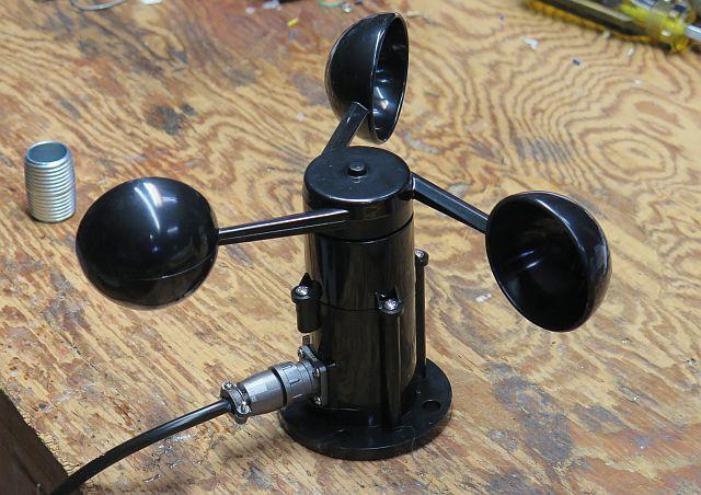 Available from several sources. This one came from Mouser.
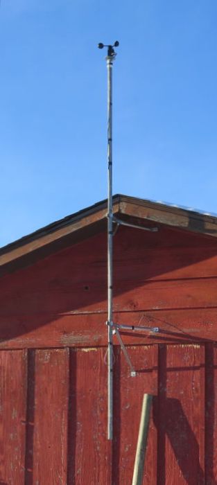
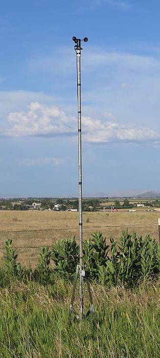
Anemometer InstallationMounting Plate and Pedestal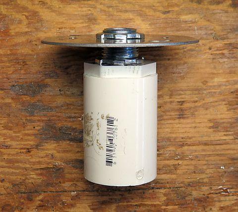
Mounted on Mast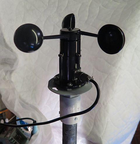 1¼"x10' (3m) TV antenna mast, secured with self-tapping screws. 
Voltage-to-Current ConverterVoltage-Controlled Current Regulator The key take-away from the specs for the 1733 is that, from a baseline voltage of 0.4 volts with no wind, its output voltage increases by 50 mV for every 1 m/s increase in wind speed, or 22 mV for every 1 MPH increase, or 14 mV for every km/h increase. The voltage continues to increase (by extrapolation) up to 3.5 V (70 m/s, 156 MPH, 250 km/h). The circuit in Figure 1 converts the output voltage from the anemometer to a corresponding current in the remote meter loop. Changing the value of the current sensing resistor (R1) changes the voltage-to-current ratio, making the circuit adaptable to virtually any DC meter. (The value of R1 is calculated using one of the equations below.) The circuit can output currents up to 20 mA. The Circuit U1a is the meter loop driver. The opamp monitors the voltage drop across R1 and supplies current to the loop sufficient to exactly offset the voltage from the anemometer. The magnitude of the current flowing in the loop is thus independent of loop resistance. U1b and the associated circuitry provide a regulated current sink for R1 and the meter loop. The circuit maintains the voltage at TP 1 at exactly 0.4 volts. Thus, when the wind is dead calm and the anemometer's output is 0.4 volts, the current through the loop will be zero. Figure 1 
The as-built voltage-to-current converter.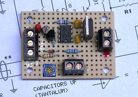 Installed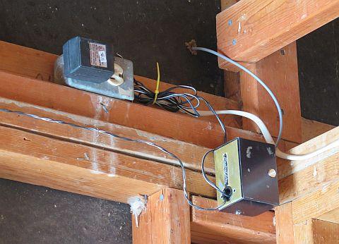 The gray wire is the cable from the anemometer. Calculating R1 (Fig 1)
Examples
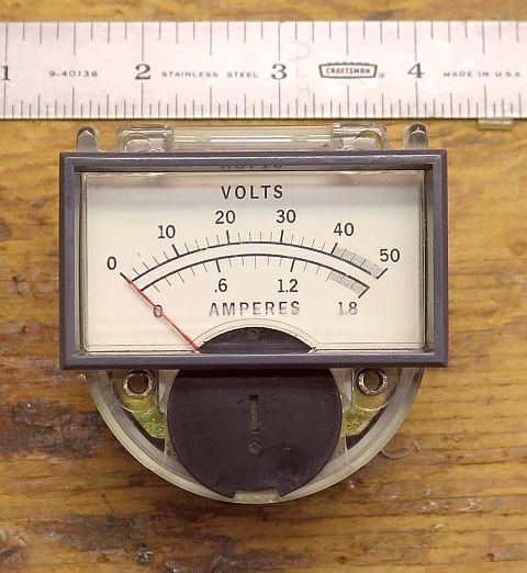
Selecting a Meter
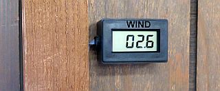
Alternate Meter Type - Digital Panel MeterThe circuit in Figure 3 can be used if a digital readout is preferred. The 49.9-ohm shunt resistor across the input terminals of the meter "converts" the current to a voltage.
Figure 3
Multiple Devices are Connected in SeriesFigure 4 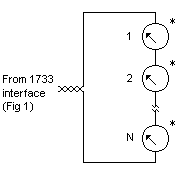 *Meters or other device/s (data logger, chart recorder, etc.), including shunt resistors. Mix or match.
|

Computer Interface
Here's a real-time working example:
|
Interface and Code Creating the real-time working example involved building a fairly simple loop-to-computer interface and writing some code: in Basic for the interface; in Perl to acquire and store the data; and in PHP/GD Graphics Library to generate the graph.
 OJ monitoring the weather. Schematics produced with DCCAD.
Related PagesLoop Current-to-Computer InterfaceWheatland, Wyoming - Wind Speed Record - Past 24 HoursExternal LinkUSB-Based 8-Channel Data Acquisition Module
 |