Old Junk Given New Mission as Remote Motion Sensor
Long-Range Wireless Gate Annunciator
Max Carter
The motivation for building this came when the county converted my rural access road from a cul de sac to a through road and vehicle traffic past my place increased by a factor of a hundred. My front gate, where the driveway meets the county road, is about 1000 feet (305m) from the house and with tree growth is becoming increasingly hard to see from the house. While my dogs make an excellent "motion-sensing/security system" when a visitor nears the house on the driveway (or otherwise), I wanted to get a heads-up when a vehicle or pedestrian passed through the gate - a preemptive doorbell.

Amongst my pile of surplus electrical/electronic junk and other stuff gathering dust, I had this particular combination of parts, most of it given to me some years ago by a friend who came up with the original annunciator idea:
- defunct IR motion sensor,
- 10 GHz Gunn oscillator,
- speed radar detector,
- 12-volt 3.5 Ah gel battery,
- photovoltaic charging panel,
- weather-proof box.

The wireless annunciator function probably could be duplicated with a currently available sensor, microcontroller and wireless modules, though I'm not sure it would work at 1000 feet. Likewise, I doubt any of the commercial [Home Depot, etc] wireless motion sensors work at that range, though I've never tried one. This approach had the advantage of being priced right - ie, cheap - with the potential of working out to a range of a mile or two. Even a wired system at 1000 feet would require a hundred dollars worth of field wire.
Anyway, the project proved to be more challenging than I thought at first, but ended up being fun and educational. You may find some of this material useful in your project or application.
The First Challenge: The Motion Sensor
Microwave Out-Performs PIR
The first couple of years of operation employed a PIR (passive infrared) sensor at the gate. I had successfully rehabilitated one of the junk PIR sensors (see: PIR sensor rebuild) but, while the installed PIR sensor worked 99% of the time, there were occasions when it didn't, usually during precipitation events (snowfall, rain, drizzle). This gave me an incentive to investigate another interesting approach. The device now installed, and described here, uses the HB100 microwave motion sensor. These are incredibly cheap: available on eBay for as little as $3. A microwave motion sensor differs from a PIR sensor in that it's an active device. Whereas the PIR sensor monitors ambient (IR) radiation impinging on the device, the microwave sensor radiates a low-power microwave beam and monitors the signal reflected from objects. The HB100 works better in adverse weather.
HB100
| Antenna Side | Other Side |
 | 
|
| Note installed header pins. |
The HB100 consists of a 10.525 GHz dielectric resonator oscillator (DRO), transmit antenna, receive antenna and Schottky diode receive mixer/detector. If an object within range is moving relative to the sensor, the reflected signal will differ slightly in frequency from the transmitted signal (the "Doppler effect"). The frequency shift depends directly on the target's speed as seen by the sensor - the greater the relative speed, the greater the shift. The received signal is mixed with a sample of the transmitted signal to derive a difference signal. The difference signal appears at the sensor's IF output pin.
IF Amplifier/Filter/Rectifier
The sensor requires an amplifier/filter/rectifier to complete the system. Figure 1 shows the circuit, derived mostly from this application note. It consists of a sample-and-hold input stage, variable gain filter/amplifier, full-wave rectifier and output buffer transistor.
Figure 1

The motion sensor is operated in pulse mode to minimize power consumption, important when the power supply is a battery. The 7555 (U2), a CMOS version of the 555, generates 20 µS pulses at 0.5 mS intervals (2 kHz 4% duty cycle). The sensor radiates only when the output pin (3) of U2 is low. This results in a 25:1 reduction in average power consumed by the sensor module, and a reduction (by 14 dB) in average radiated power. After adding in the power consumed by U2, average current draw is about 5 mA, compared to 50 mA the sensor would draw in continuous mode. (See CW circuit.)
Pulse mode could be thought of as a form of spread-spectrum, a technique used in wireless communications systems to minimize interference. The synchronous sample-and-hold input to the IF amplifier operates as a 'matched filter' to de-spread the received signal, making it appear to the amplifier/filter as a continuous, low-frequency signal. This compensates for the reduced transmitter power and may provide some interference rejection. Note that the sample-hold transistor (2N2222) operates in reverse active mode during part of the sample cycle. [Google: "bjt reverse active mode"]
The IF signal from the sensor is amplified and filtered by opamps U1a and U1b. Gain can be adjusted from about 1000 to 10,000 (~60-80 dB). Frequency response is ~5-50 Hz, making the sensor most sensitive to speeds in the range of 0.15 to 1.5 MPH (0.25-2.5 km/h), walking speed. (For more on the speed range issue, see 'Lessons Learned' below.) The output of U1b is fed to U1c and U1d. When the signal exceeds 1 volt peak-to-peak amplitude, one or both 1N914 diodes conduct, charging the 100 µF capacitor and turning on the NPN output transistor. The output is pulled to ground when a moving object is detected.
IF Amplifier Gain vs Frequency

| IF amplifier as-built | Mated to HB100 |
 Note the four 2-pin headers. These accept the pins on the HB100. |  |

The Microwave Link
Remote End:
The Gunn oscillator is at the head end of the communications link used to send the status of the motion sensor to the monitoring location (the house). A single bit of information is transmitted: The transmitter is off when no motion is detected by the motion sensor; the transmitter is turned on when motion is detected. This particular device (New Japan Radio Co NJR4104) operates in the X-band.
X-band Gunn Oscillator

It's a pretty simple device - though don't ask me to explain the quantum mechanics (see Wikipedia). The oscillator consists of a Gunn diode mounted in a resonant cavity. The diode and cavity act as a relaxation oscillator when the diode is forward biased at a certain voltage (around 8Vdc). The current draw is around 110 mA (880 mW). The RF output from the cavity is about +12 dBm (16 mW). The oscillator frequency, nominally 10.525 GHz, can be varied slightly by varying the biasing (power supply) voltage. The cavity also includes, in addition to the Gunn diode, a mixer diode used for detecting an incoming microwave signal. Thus the device is a transceiver and probably would normally be part of a speed radar or microwave motion detector. The receive function is not used in this application. While this particular oscillator was a freebee, similar oscillators are often seen on eBay for around $25.
Gunn Driver
Figure 2

The output of motion sensor is pulled low when motion is detected. This causes 2N2907A transistor to conduct, applying 8 volts DC to the Gunn oscillator.
Antenna
Microwave communication requires a line-of-site path, or nearly so. In tests with the radar detector described below, the Gunn oscillator without an antenna could be detected at a line-of-site distance of around 2000 feet (610m). While this sounds like it would be more than adequate at 1000 feet, it is only 6 dB above the detectable level, and since the working location is not strictly line-of-site from the house, with lots of microwave-absorbing growing trees blocking the path, and because I wanted the receiver to be capable of reliably operating at varying locations within the house (not just near a window), I decided to equip the oscillator with an antenna. The horn antenna, shown in the photo below, bought on eBay, provides 17 dB gain over the bare oscillator.
WR90 Antenna

Antenna Mated to Gunn Oscillator

Equipped with the antenna, the system line-of-site range theoretically increases to about 2.7 miles (4300m), fade margin at 1000' increases to 23 dB.
Receive End:
X-band Radar Detector

This appears to be an X-band only speed radar detector, the kind of thing widely available at truck stops before police radars moved to higher frequencies and began employing more sophisticated techniques. It's equipped with an LED bargraph signal level indicator, a 2-position sensitivity switch ("HWY" and "CITY" settings) and an audible alarm that sounds when a signal in the X-band is detected. For optimal sensitivity the detector must be oriented with the rear of the unit facing the microwave signal source. The unit requires +12 Vdc at 250 mA. That's about all I know about it. It works. (I see a 3-band version of the device on eBay for about $20.)
Power
Remote Power:
With the motion sensor circuitry requiring a few milliamps continuously and the Gunn oscillator about 110 mA intermittently, the 3.5 Ah gel (sealed lead-acid) battery is more than adequate for powering the remote end of the annunciator system. If one were building this thing with new parts, a string of NiMH AA rechargeables might be a better match to the power requirements, but the gel battery was available.
Gel Battery

Solar Panel
At 200-300 mA output current when the sun is shining, this is likewise probably overkill, but again the price was right.

Charger/Regulator
As-Built Constant-Voltage Charger-Regulator Circuit
Figure 3

|
*Remove jumper J1 (Figure 4, temperature compensator, below) select R1 for 14.06V measured at the battery terminals; reinstall J1. If the temperature compensator circuit is not used (nothing connected to A, B or C), select R1 for 13.6V measured at the battery terminals. |
The LM317 regulator (U2) provides constant-voltage (CV) charging for the gel battery. The regulator is set to charge the battery at its optimal float value, 13.6 volts, at 20°C (68°F). The battery may never actually reach a full charge at that setting but will come very close over time. The float setting is very easy on the battery, which is good for long battery life. U2 is set to slightly higher output to allow for a 0.35 volt drop across the 1N5817 diode. The diode prevents the battery discharging through the charging regulator and solar panel when the sun is not shining. Due to the approximately 2.35-volt dropout headroom requirement of the LM317 regulator (U2) and 1N5817 diode, the battery charging regulator circuit does not charge the battery during heavily overcast sky conditions. Fortunately, the current requirement for the annunciator system is low, the battery capacity large, and the number of heavily overcast hours in a year at this location low; the battery stays adequately charged.
Charger/Gunn Driver Interconnect Board

Temperature Compensator
Gel batteries have a lot of advantages, but they're a bit fussy regarding charging voltage, especially in outdoor situations where ambient temperature is not controlled. The compensator circuit below varies the charging voltage inversely with battery temperature.
As-Built Temperature Compensator Circuit
Figure 4

 |
|
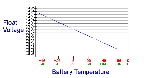
The the output voltage of the LM34 temperature sensor (glued to the battery) drives a voltage-to-current converter, the output of which pushes or pulls current into or out of the adjustment node of the LM317 charging regulator, varying its output voltage. The component values are selected so as to vary the charging voltage inversely with battery temperature by .012 volts per °C (-2 mV/cell/°C), with 14.05 volts at -17.8°C (0°F) as the baseline reference. Charging voltage will be 14.33V at -40°C, 13.37V at +40°C,.
Temperature Compensator Board
The temperature compensator was an afterthought, so it ended up on a separate board which plugs into the regulator board.

Charger/Gunn Driver, Temperature Compensator, LM34, Battery

|
For a couple of other battery and charger options see |
Remote Interconnect Diagram
Figure 5

Receiver Power:
No problemo. An old wall wart does the job of converting 120-volt AC service to the 12 Vdc required by the radar detector. Grid power simplifies things.
Wall Wart

The Installed System
The Remote End:
Battery, Charger/Gunn Driver, Temp Compensator, Gunn Oscillator Installed in Weather-Tight Box
The antenna is glued to the side of the box. The box is made of a non-metallic material, so is transparent to microwaves. The box is oriented so the microwave beam is directed toward the house. (The orientation is not super-critical.)

Solar Panel Mounted

Motion Sensor Mounted on Gate Post

The sensor is connected to the Gunn driver through a short run of buried 3-conductor cable.
The Receive End:
The Installed Receiver

The microwave receiver (radar detector) works well in the house, though the signal level varies from location to location. As expected, the number of walls and thickness of walls between the gate remote and the radar detector are predictive of signal strength - more wall, less signal. There are a few dead spots where the signal is below detectable level. Unfortunately, a location I'd had high hopes for on some shelving convenient to an AC outlet and centrally located, is one of those spots. I ended up placing the unit at a location slightly less convenient but with an adequate signal. The installation was made in the winter months when the (deciduous) trees were leafless. It remains to be seen how well it all works during summer months. [Update: The microwave link continues to function in the summer months, though with somewhat reduced received signal level.] The receiver was later connected through a beep/siren power amplifier to an external speaker system which allows the receiver to be heard in outbuildings.
Foreign Signals
Before installing the system, I thought signals from automatic door openers, police radars and the like might cause falsing of the radar detector, indicating a gate entry when there was none. This has proved not to be a problem. Whatever 'foreign' signals are out there apparently are too weak. The microwave oven in the kitchen, 25-30 feet from the detector, occasionally elicits a short beep on power-up.
You may be wondering...
Since the HB100 sensor and the microwave link (Gunn osc./radar det.) operate on the same frequency, why don't they interfere with each other?
Microwave Sensor to Microwave Link:
There are several reasons, any one of which probably would be enough to prevent interference - trees obstructing the microwave sensor's path to the receiver (radar detector), lower effective radiated power from the microwave sensor, cross polarization discrimination (XPD) in the receiver - but the killer reason is this:
- The speed radar detector (the receiver) is set to its CITY mode. In this mode it becomes blind to the signal from the HB100. The HB100's transmissions are apparently too short in duration (20 µS) and/or spaced too infrequently (4% on, 96% off) to be detected. I don't know the designers' rationale for the receiver's CITY mode, but the effect is to make the Doppler sensor's signal invisible to the device.
Microwave Link to Microwave Sensor:
Possibilities include path loss, the directional nature of the two systems' antennas, and XPD, which together provide 75-80 dB of isolation. The main reason however, I think, is this:
- While the two systems nominally operate on the same frequency, they are not actually on the same frequency. The receiver in the microwave sensor is extremely selective, having a bandwidth on the order of 50 Hz. The chance that the Gunn transmitter is operating within 50 Hz of the microwave sensor is virtually nil. The matched-filter/sample-hold IF input may also provide some interference rejection.
Lessons Learned
- The motion sensor should be mounted horizontally (as shown in the photos above) for best performance. In this position, the sensor radiates a horizontally polarized signal.
- Mount the sensor 30-36" (75-90cm) above the roadway level. Mounting any higher may allow some small cars to pass without detection.
- To avoid nuisance trips, the sensitivity control [SENS] should be set no higher than what is necessary for reliable detection. A setting near the low end of its range will likely be optimal for detecting vehicles in an outdoor environment.*
- Beware of nearby metallic objects moving in the wind. A bouncing strand of barbed wire on the rear side of the sensor caused false alarms until it was secured.
- Installed at its initial location, the sensor was exquisitely sensitive to pedestrian motion, but was virtually blind to vehicle motion! Why? I soon learned that the sensor was discriminating against the speed of the targets' motion. As explained above, the IF amplifier discriminates against speeds above about 1.5 MPH. The fix was to relocate the sensor so as to place its axis at a less acute angle to the direction of travel. The angle was increased from about 10° to about 80°. See illustration below:

The sensor "sees" the target's speed multiplied by the cosine of the angle between the target's moving direction and the axis of the module (see app note). At the new angle (80°), the ratio of actual speed to apparent speed is increased by a factor of about 5.7 [cos10/cos80] over the original angle, an improvement of nearly six-fold. Given the ±45° width of the sensor's beam, vehicles passing through the gate travelling at almost any speed now fall within range of the IF amplifier's frequency response and are easily detected.
Note that the ability to discriminate based on the target's speed would also be useful in detecting pedestrians while ignoring vehicles. In that case, the original 10 degree beam angle might be near optimal.
System Detects Unauthorized Entry!
Very early one morning the sensor caught something passing through.
Deer? Coyote? Raccoon? Sasquatch?
Tracks in the snow implicate the perpetrator..

Actually, deer, not rabbits, are the most bothersome. Herds tend to move in single file and a herd of 10 travelling through the gate might trip the system 5-10 times as they come through. Very annoying.
*Choosing Cars over Critters
The microwave motion sensor reliably detects moving vehicles and animals, even during damp weather events (unlike the PIR sensor). I took advantage of the microwave sensor's uniform performance and lowered its sensitivity setting to a point where cars are detected but critters are not. Yes, by lowering the sensor's sensitivity I am choosing to ignore pedestrians (human critters) but, this being a rural location, visitors very rarely if ever arrive on foot. The ability to detect pedestrians can be restored to the sensor if needed simply by readjusting the sensitivity setting upward.
Schematics produced with DCCAD.
Related Articles
Microwave Motion Sensor
Temperature-Compensated Solar Battery Charger
PIR-Sensor Rebuild Project
Beep/Siren Power Amplifier