This circuit was built to amplify and distribute the relatively low-volume beeping tone produced by an annunciator system to a wider area through several horn-type loudspeakers. You may find the circuit(s) useful for that purpose or as a self contained, high-powered beeper. The amplifier circuit would also be useful to increase the volume (or distribute widely) the output from a siren circuit [a siren sound is a continuous tone that varies in frequency].
Powered with the specified 13.6-volt power source, the basic circuit delivers about 5 watts to each 8-ohm (a typical horn driver impedance) speaker paralleled in a system: 2 speakers, 10 watts; 3 speakers, 15 watts; and so on up to a maximum of 40 watts into 8 speakers (1 ohm equivalent resistance). Five watts of squarewave 'beep power' from a horn loudspeaker is VERY loud - something like 110-115 dB, loud enough to be easily heard a quarter mile (400m) away or more.
Four versions of the circuit can be built: 1) a basic low-gain amplifier, 2) a high-gain version, including a no-connection variation, 3) a self-generating version and 4) a high-power version, 6 dB louder.
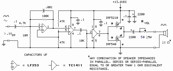
Basic Beep Amplifier
Figure 1
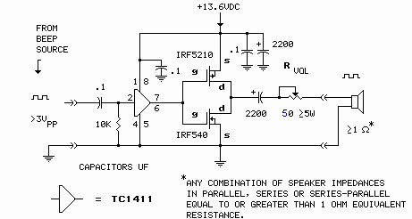
- This circuit accommodates the most common situation where a logic-level (TTL, microcontroller, etc) squarewave beep/siren signal is available from the alarm equipment. The circuit requires a minimum 3 volt peak-to-peak amplitude input signal.
- The output is a squarewave, degrading to a sawtooth under heavy load (<1Ω) - strictly Lo-Fi.
- With no input signal (system on standby, waiting for a beep), at 13.6V power supply voltage, the amplifier draws less than 50 µA power supply current.
- Power supply current draw when operating (beeping) depends on speaker impedance and Rvol setting. At minimum Rvol resistance, supply current draw will be 3.4/R, where R is the measured or calculated resistance of the speaker system. Typically, supply current will be 0.425A for each 8-ohm speaker paralleled in the system: 0.85A for 2 speakers; 1.275A for 3; and so on up to 3.4A for 8 speakers.
- Maximum output power will be 46.24/R, where R is the measured or calculated resistance of the speaker system.
- Note that the output transistors are not the same. They are complementary P-channel/N-channel types: P-channel (IRF5210) upper, N-channel (IRF540) lower. Any high current P-channel/N-channel MOSFET pair having an Rds (ON resistance) one-tenth the expected speaker system resistance or less, and reasonably matched (≈Rds), can be used in the circuit.
- Rvol is optional, needed only if a master volume control is required. A setting at other than maximum output (≠0 ohms) will produce lower output power.
A tapped wirewound ceramic resistor (resistance about 10x speaker system resistance) is the device of choice for Rvol. Another option for volume control would be to install a resistor (fixed or variable) in series with each individual loudspeaker.
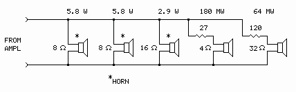
Speaker System - All 8Ω Drivers

- Speakers need not be 8 ohms. ANY combination of impedances, in parallel or series-parallel, can be driven by the amplifier as long as equivalent resistance is 1 ohm or greater. Calculate using reciprocal addition, or simply measure speaker system resistance (R) with a multimeter.
The as-built system, for example, consists of two 8-ohm speakers, a 16-ohm speaker, a 4-ohm speaker with a 27-ohm fixed resistor in series, and a 32-ohm speaker with a 120-ohm fixed resistor in series. The system calculates to about 2.8 ohms and measures 3.4 ohms (wire resistance is also a factor).
As-built Example - Mixed Impedances
Calculated individual speaker power is shown. Actual powers are slightly less due to wire resistance.
Wire
Most speaker installations can be wired with AWG 18 lamp cord with good result. Use the clear, small-gauge "speaker wire" only for short runs. An installation with very long runs, or one that uses the 160-watt amplifier (below), might require wire larger than AWG 18. In those cases consider using AWG 16 or 14 Romex or plenum-rated cable as required by wiring codes.
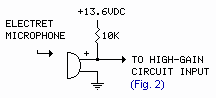
High-Gain Version
This circuit adds a gain stage ahead of the basic amplifier circuit to accommodate a lower input signal level, sinewave or squarewave.
Figure 2
Notes:
- Input signal must be greater than 100 mV peak-to-peak amplitude.
- Input signal can be a sinewave or squarewave.
- Standby power supply current draw increases to about 4 mA (bummer).
- All notes for the basic circuit (Fig.1), except the input signal requirement and standby current, apply to the high-gain circuit.
No-Connection Variation
A reader suggested this. It requires no electrical connection to the alarm equipment:
- Tape or glue the microphone over the sounder on the alarm equipment.
- The loudspeaker(s) should be isolated from the microphone to prevent feedback. Pad the volume down with a resistor (Rvol) if feedback is a problem.
- As mentioned above, the amplifier is a Lo-Fi device. The output may not retain the overtones of the original sounder. (This is a problem?)
Self-Generating Version
If your system supplies only a contact closure, open collector, or DC voltage during an alarm event, not the actual beep signal, to, say, power a self-contained sounder or relay, the circuit in Figure 3 can generate its own beep tone in response.
Figure 3
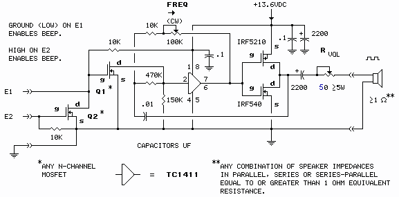
Notes:
- There are 2 options for enabling the beep tone generator: ground on E1 produces beep; or high (≥5V) on E2 produces beep. Open circuit on both inputs silences beep.
- Virtually any N-channel (enhancement mode) MOSFET will work for Q1 and Q2. VN2222s and VN10KMs are cheap.
- If E2 input will not be used, Q2 and associated 10k resistor can be deleted.
- Beep tone frequency can be varied from about 500 Hz to about 4500 Hz.
- All notes for the basic amplifier version (Fig. 1) apply to the self-generating version, except the input signal requirement.
High-Power (160-watt) Output Version
This variation on the basic amplifier circuit shown in Fig 1 adds a second pair of complimentary output transistors connected as a classic H-bridge. The result is a quadrupling of output power. The high-power output circuit can be substituted for the output section in any of the versions above. It would be up to you to decide if the extra 6 dB of loudness is worth the effort.
Figure 4
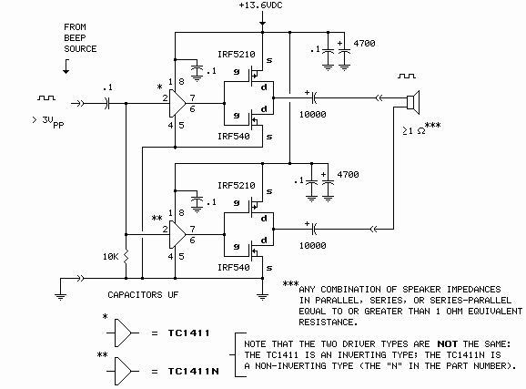
Notes:
- Output power is 185/R, where R is the resistance of the speaker system (measured or calculated); about 20 watts for each paralleled 8-ohm speaker, about 160 watts for 8 speakers.
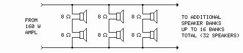
- The amplifier could also be used to power up to 32 speakers at 5 watts each in a series/parallel configuration.
5-Watt Series-Parallel Example
- Power supply current draw is 13.6/R, where R is the resistance of the speaker system (measured or calculated); about 1.7 A for each paralleled 8-ohm speaker; about 14 amps for 8 speakers. (Definitely consider the battery-based power supply below.)
- Use heatsinks on the output transistors if the amplifier will be used for siren service.
- Note that the two driver types are NOT the same: the TC1411 is an inverting type; the TC1411N is a non-inverting type. Datasheet (PDF).
- All notes for the basic amplifier (Fig 1), except output power, power supply current and references to drivers and heatsinks, apply to this variation.
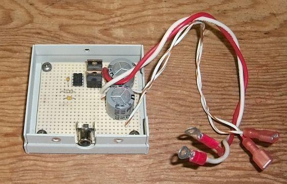
As-Built Basic Amplifier
Master volume control Rvol not used.
Heatsinks on output transistors not required.
Suggested Power Supply
The system can certainly be powered with a 12-volt, 4-amp power supply, but, given the tiny standby current requirement and infrequent occurrence of the beep signal (let's hope), the approach below seems more practical. It's simply a 12V gel (sealed lead-acid) battery with a trickle-charger. It idles at a few milliamps most of the time but can deliver many amps when needed to power the beeper amplifier. The battery should last for many years at this gentle charge rate, and of course gives the amplifier the ability to operate during a power outage.
Figure 5
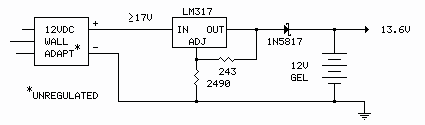
- Virtually any DC wall wart will work for this as long as its open-circuit output voltage is 17 volts or greater.
- The gel battery need have only minimal capacity (Ah) for this application, though any capacity should be satisfactory - use what you have. Expect a large-capacity battery to take a long time to charge initially with this charger.
Schematics produced with DCCAD.
Related Article
Long-range Gate Annunciator
