Charger Pampers Remote Power Battery
Temperature-Compensated Solar Battery Charger
Maintains 12-Volt Gel Battery in Extreme Temperature Environment
Max Carter
This article describes a power supply built for a remotely-located outdoor project requiring 12 volts DC at a few milliamps continuously and about 110 mA intermittently. A 12-volt 3.5 Ah gel (sealed lead-acid) battery was available, more than adequate for powering the remote system, but I needed a way to keep it charged. As it happened I had also on hand a 5-watt "12-volt" photovoltaic charging panel. At 200-300 mA output current when the sun is shining, the solar panel was overkill, but it was acquired at no cost, so the price was right. It was an obvious choice.
Gel batteries have a lot of advantages, but they're a bit fussy regarding charging voltage, especially in outdoor situations where ambient temperature is not controlled. Cooking and freezing are the main reasons for the notoriously short lives of gel batteries in outdoor situations. The system had to be designed so that both over-charging on hot summer days and under-charging in mid-winter are avoided.
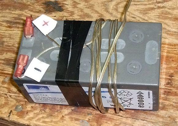
Gel Battery
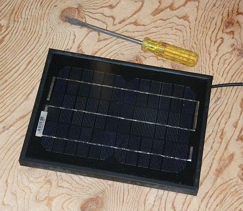
Solar Panel
Basic Constant-Voltage Charger-Regulator Circuit
Figure 1
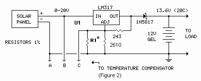
*The value of R1, in parallel with the 2610-ohm resistor, determines the regulator's uncompensated charging voltage. This voltage is set to a reference based on the sensor type used in the temperature compensator circuit (Figure 2 below). Use the calculated value from Table 1, or determine the value experimentally by following the steps in Table 2.
Table 1
Calculated Values for R1
Values shown assume .35V drop across 1N5817 and 1.25V LM317 reference voltage.
| Temp sensor option: | LM34 | LM35 | None (no temp. compensator) |
| Reference temp: | 0°F | 0°C | 68°F/20°C |
| Reference voltage: | 14.05V | 13.85V | 13.60V |
| Calculated R1 (nearest 1% std. value): | 124k | 71.5k | 45.3k |
Table 2
| Experimental Method for Selecting R1 |
|---|
|
The LM317 regulator (U1) provides basic constant-voltage (CV) charging for the gel battery. The regulator is set to charge the battery at its optimal float value, 13.6 volts, at 20°C (68°F). The battery may never actually reach full charge at that setting but will come very close over time. The float setting is very easy on the battery, which is good for long battery life. The 1N5817 diode prevents the battery discharging through the charging regulator and solar panel when the sun is not shining.
Due to the approximately 2.35-volt dropout headroom requirement of the regulator and 1N5817 diode, the solar panel circuit may not charge the battery during heavily overcast sky conditions. Fortunately, the current requirement for the installed system is low, the battery capacity large, and the number of heavily overcast hours per year at this location low; the battery stays adequately charged.
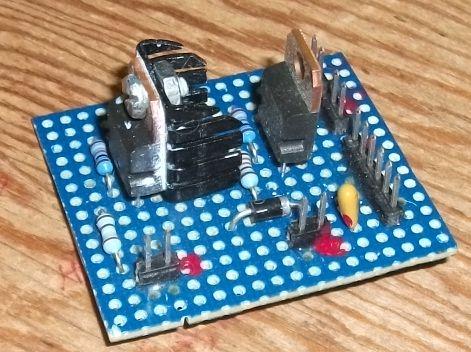
Charger-Regulator Board
The LM317 charge regulator is on the left. The small heatsink shown provides adequate cooling for regulating the 5-watt solar panel. With a larger heatsink, the LM317 can handle 12-volt panels up to 25 watts. A second LM317, on the right (not shown in Figure 1), regulates the battery voltage to the voltage required by the load.
Temperature Compensator
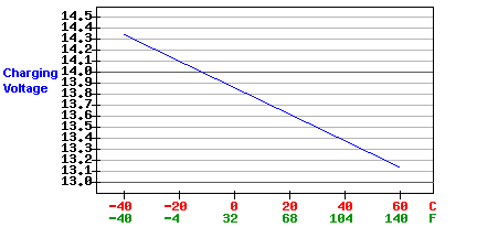
The compensator circuit below varies the charging voltage inversely with battery temperature by .012 volts per cell per °C
(-2 mV/cell/°C).
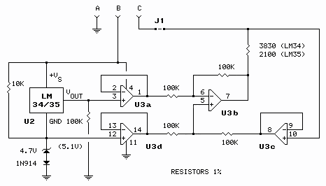
Temperature Compensator Circuit
The circuit can be implemented with either an LM34 (°F) or LM35 (°C) temperature sensor.
Figure 2
 |
|
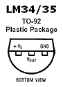
The the output voltage of the LM34/35 temperature sensor (glued to the battery) drives a voltage-to-current converter, the output of which pushes or pulls current into or out of the adjustment node of the LM317 charging regulator, varying its output voltage.
Temperature Compensator Board
The temperature compensator circuit is built on a separate board which plugs into the regulator board.
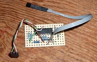
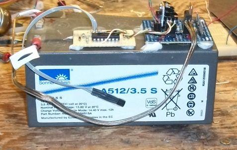
Charger-Regulator, Temperature Compensator, LM34, Battery
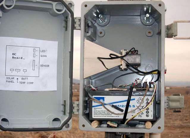
Battery and Charger Installed in Remote
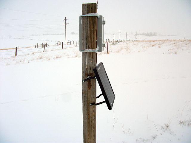
Mounted Solar Panel (fixed mounting)
28 degrees off vertical, facing due south, is optimal at this latitude (42°N) for maximum year round solar-electric energy conversion [optimal during the winter months and more than adequate at other times of the year]. This panel is set at about 23 degrees, sub-optimal but still adequate. [In other words the battery stays charged year round.]
Related Article
Long-Range Wireless Gate Annunciator
