MPX96 FM Stereo Transmitter
Setting Frequency Programming Switches
If using ODD frequency spacing (97.1, 97.3, 97.5, etc):
- Verify Jumper JP1 is in the ODD position (JP1 not installed; pin 11 of IC7 open).
- Subract 0.1 MHz from the desired operating frequency (example: 97.1 - 0.1 = 97.0).
- Multiply by 5 (97.0 x 5 = 485).
- Convert that number to binary. This must be a 10-digit number. Add leading zeros if necessary (48510 = 01111001012). calculator
- Program the switches.
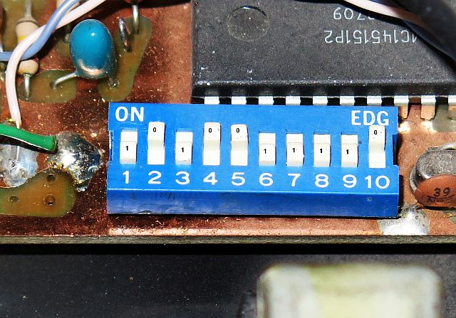
- A switch in the "on" position programs a zero (0); a switch "not-on" programs a one (1).
- Switch 10 is the Most Significant Digit (MSB). Start at switch 10 and work towards switch 1, the Least Significant Digit (LSB). This is of course BACKWARDS from what you might expect. (Or maybe I installed the switch backwards.) The photo below shows the switch as installed and programmed per the example (97.1).
If using EVEN frequency spacing (97.0, 97.2, 97.4, etc):
- Verify Jumper JP1 is in the EVEN position (JP1 installed; pin 11 of IC7 grounded).
- Multiply desired frequency by 5 (97.0 x 5 = 485).
- Convert that number to binary. This must be a 10-digit number. Add leading zeros if necessary (48510 = 01111001012). calculator
- Program the switches.
- A switch in the "on" position programs a zero (0); a switch "not-on" programs a one (1).
- Switch 10 is the Most Significant Digit (MSB). Start at switch 10 and work towards switch 1, the Least Significant Digit (LSB). This is of course BACKWARDS from what you might expect. (Or maybe I installed the switch backwards.) The photo shows the switch as installed and programmed per the example (97.0).
Frequency Programming DIP Switch, as Installed
- Verify Jumper JP1 is in the ODD position (JP1 not installed; pin 11 of IC7 open).
- Subract 0.1 MHz from the desired operating frequency (example: 97.1 - 0.1 = 97.0).
- Multiply by 5 (97.0 x 5 = 485).
- Convert that number to binary. This must be a 10-digit number. Add leading zeros if necessary (48510 = 01111001012). calculator
- Program the switches.
- A switch in the "on" position programs a zero (0); a switch "not-on" programs a one (1).
- Switch 10 is the Most Significant Digit (MSB). Start at switch 10 and work towards switch 1, the Least Significant Digit (LSB). This is of course BACKWARDS from what you might expect. (Or maybe I installed the switch backwards.) The photo below shows the switch as installed and programmed per the example (97.1).
- A switch in the "on" position programs a zero (0); a switch "not-on" programs a one (1).
- Verify Jumper JP1 is in the EVEN position (JP1 installed; pin 11 of IC7 grounded).
- Multiply desired frequency by 5 (97.0 x 5 = 485).
- Convert that number to binary. This must be a 10-digit number. Add leading zeros if necessary (48510 = 01111001012). calculator
- Program the switches.
- A switch in the "on" position programs a zero (0); a switch "not-on" programs a one (1).
- Switch 10 is the Most Significant Digit (MSB). Start at switch 10 and work towards switch 1, the Least Significant Digit (LSB). This is of course BACKWARDS from what you might expect. (Or maybe I installed the switch backwards.) The photo shows the switch as installed and programmed per the example (97.0).
- A switch in the "on" position programs a zero (0); a switch "not-on" programs a one (1).
Frequency Programming DIP Switch, as Installed
