Find on this page  |  Range Calculator/Estimator

High Fidelity

Laser Pointer Audio Modulator - Laser Beam Detector/Demodulator

Modulate a cheap laser pointer with voice or music.

Max Carter


If you'd like to experiment with point-to-point (free-space, without a glass fiber) light-beam voice or other audio communications, or with music transmission (say, to a remote clandestine radio transmitter), these circuits might be of interest to you. The high-fidelity circuits employ a cheap laser pointer as the light source and a readily available photodiode as the detector. The system has been successfully demonstrated to a distance of 6.5 miles (10.5km).

Lasers are inherently non-linear devices; laser diodes happily operate only in a narrow range of drive currents. Too little current and the diode refuses to "lase". Too much and the diode self-destructs. Thus, efforts to directly modulate a laser with an analog signal are usually unsatisfactory. The vast majority of laser modulators are of digital design; the modulator switches the laser between two discreet current levels, conveying information in the data encoded in the drive signal. In this case, the 'data' is an FM subcarrier operating at around 75 kHz, and the laser current levels are 0 and 30 mA (adjustable).

Likewise, photodetectors operating in the real world of ambient light noise sources, without benefit of a glass fiber transmission medium, suffer from non-linearities of their own. The FM subcarrier is for the most part immune to detector non-linearity.

The transmitting circuit is shown in Figure 1.

Figure 1

The circuit uses a method of generating FM called slope modulation. Integrator U1a, comparator U1b and limiter U3 form a free-running FM oscillator/modulator operating at twice the operating output frequency. Integrator U1a is the heart of the modulator. The output of U1a is a linear ramping voltage of either positive or negative slope. The slope is determined by 1) the value of the integrating capacitor connecting pins 13 and 14 of U1a and 2) the sum of currents from U1c, U1d and FREQ ADJ and LINEARITY ADJ potentiometers at the summing point (pin 13) of the integrator. Negative feedback current from U2, through the FREQ adjust potentiometer, causes the circuit to oscillate at a frequency determined by the combined positive and negative slopes of the U1a output signal. The output signal (U1a pin 14) is a non-symmetrical (scalene) triangle wave. The degree of asymmetry determines the period and thus the frequency of the output signal; the greater the asymmetry, the lower the frequency. By controling the integrators's output slope, the combined input currents (from the above-mentioned sources) determine the instantaneous oscillator frequency.

The output signal from U1a is presented to comparator U1b. The output of U1b will either be 'high', near the power rail voltage, or 'low', near ground, depending on whether the pin 9 voltage is above or below the reference voltage on pin 10. Limiter U2 shortens the rise and fall times of the U1b output signal. U2 provides the negative feedback signal to the integrator, as explained above, and also clocks output divider U3a. U3a divides the signal frequency by 2 and restores symmetry.

U4 is the laser driver. When the output of the D flip-flop (U3a) is low, the driver connects the laser current supply to the 4.7 uF coupling capacitor. This causes the lower Schottky diode to conduct, charging the capacitor. When the D flip-flop is high the driver connects the capacitor to the ground rail. This discharges the capacitor and causes the upper diode to conduct. The discharge current is delivered to the laser pointer. The driver's internal resistance and the forward voltage drop of the diodes work in conjunction with the pointer's internal resistor to limit current flow through the circuit. Laser current can be monitored with a multimeter connected to TP4 and TP5. Current flow from the current regulator is actually one-half the instantaneous current flow through the laser diode, since laser current flows for exactly one-half of the time. The 2-ohm scaling resistor establishes a nominal one-to-one voltage drop to instantaneous laser current relationship. Current through the laser diode causes it to produce coherent light of a wavelength and dispersion typical of a laser diode. The output of the laser diode is a series of light pulses in step with the output of the FM subcarrier generator.

Alternate Laser Drive Options

Hot Pointer Shell

The negative drive scheme shown in Figure 1 was chosen because the cheap laser pointer used has the laser diode anode connected to the pointer body (positive ground). The Fig 1 approach seemed simpler than providing a negative power rail or converting the entire modulator circuit to positive ground. If the hot pointer body is not a concern, the driver could be as simple as an open-collector NPN transistor. The mosfet driver, coupling capacitor and Schottky diodes (U4, C7, D1 and D2) shown in Fig 1 would not be needed:


Positive Grounding

If you prefer having the body of the laser pointer grounded, the simplest approach in concept (though not necessarily simple in execution) would be to wire the entire laser modulator circuit as a positive-grounded system and use a PNP transistor as the driver. The connection to the laser pointer would look like this:

The laser is simply a cheap key-chain laser pointer. In order to work with the pulse modulator, the laser must be of the type not equipped with active current regulation. In other words CHEAP. (Given a choice of laser pointers, would-be builders of this circuit should select the CHEAPEST one available - buy several.) Cheap pointers are equipped only with an internal fixed-value current-limiting resistor (value around 50 ohms). At the time of this writing, such a pointer was available here, also here. You might also find one at your local 'dollar' store.

A Note About Pushbutton Switches

Builders should be aware that the pushbutton switches on cheap laser pointers are unreliable (in my experience). Simply taping down the switch may produce erratic functioning of the laser diode, attributed falsely to failure of the diode. If you find the pointer beginning to act erratically or appearing to fail, remove the tape and exercise the switch repeatedly and see if performance improves. Builders might consider bypassing the pointer's switch. If you do that, be sure to NOT bypass the pointer's current limiting resistor. Unfortunately, accessing the little circuit board in the pointer on which the pushbutton switch is mounted will require cutting into the pointer's outer shell, possibly causing the pointer's destruction. Proceed with care.

Line and microphone amplifiers U1c and U1d amplify and isolate their respective input signals and present them, via the 100k resistors, to the slope modulator, as explained above. The amplifier circuits also each introduce a 6 dB per octave high-frequency pre-emphasis, starting at around 1600 Hz.


Prototype laser pointer modulator.

The black thing on the left is a condenser microphone. The yellow thing at the top is a cheap laser pointer (the pushbutton on the pointer, on the far side of the yellow body in the photo, is taped down for operation). The gray cord at the lower right is for connecting to a 12-15v DC power source.


Here's a Laser Shotgun to mount your cheap laser pointer in.

If you'd rather use a standard 650nm laser diode:
click here for wiring and mounting info.


Reception

Detection (reception) of the laser pulses is accomplished with a photodiode. The received signal is filtered and demodulated to recover the original audio signal. The circuit for the receiver used with the laser modulator appears in Figure 2 below.


Figure 2

Other photo diodes can probably substitute for the API device suggested. Be sure to select one that is sensitive to visible light (also called 'blue enhanced').

The detected 75 kHz optical signal from the photodiode is coupled to the base of 2N2222 transistor which selectively amplifies the detected signal by a factor of about 200 and presents it to amplifier U1a. U1a amplifies and delivers the signal through limiter U2 to one-shot multivibrator U3a. U3a outputs pulses of fixed length (time duration) to integrator U1b. The output of U1b is an analog voltage that represents the density of the input pulses - more pulses (higher input frequency) generate a higher voltage; fewer pulses (lower input frequency) generate a lower voltage. Thus the frequency-modulated input signal is converted back to the original transmitted analog audio signal. The integrator introduces high-frequency de-emphasis (roll-off) above about 1600 Hz. This roll-off is compensated for by complementary pre-emphasis in the audio amplifiers in the above (Fig 1) modulator. LP filter U1c, as shown, cuts off at about 16 kHz to allow for music transmission. See note 1 if a more restrictive frequency response is needed.


Squelch
[Thu Oct 5 14:40:48 2017] viewcoms.

Hi Max,

Have you tried adding a squelch? We use these circuits in a demo for the Texas A&M physics festival, but when showing that the laser is actually what's transmitting the signal (by blocking the beam), but it's pretty miserable to have so much noise from the speakers when we do. Any recommendation?

Thanks,
Ben

[378]


[Mon Oct 9 14:26:59 2017] viewcoms.

Ben,

I presume your demonstrations take place at short range. Try adding the resistor, circled in red below, to pin 1 of U2. Try lower values if 1 meg doesn't work, or you could use a pot to make it adjustable:


Regards,

Max

[811]

(See also the construction note below.)


Prototype Laser Pointer Receiver

The photodiode is above the receiver, mounted on a camera tripod.
Earbuds are shown connected to the receiver in this shot. The receiver can also be connected to a speaker or line input.


Note on Detector/Demodulator Construction

Due to its very high gain, the input amplifier portion of the detector/demodulator circuit is prone to breaking into oscillation if it's not properly laid out and shielded. The prototype detector/demodulator was constructed using point-to-point wiring on proto board with insulated copper foil shielding on the back side.

While this worked OK, prospective builders should consider the board layouts by Mr John West shown here, or something similar. An important feature of his boards is that they are double-sided, with the backside acting as a shield. He successfully built and demonstrated (at ham radio gatherings) several working modulator/demodulator pairs using his design.


Close-up of the mounted photodiode.


Beam concentration can raise the signal to noise ratio of the detected optical signal, and may be necessary, depending on the transmitter-to-receiver distance and other factors. Here's a Laser Beam Concentrator to mount your photodiode in for increased sensitivity and range. The concentrator was successfully used with the prototype modulator/demodulator system to establish an audio link over a distance of 6.5 miles.

Photos of System DX Tests
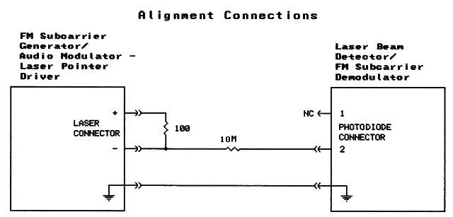

System Alignment

The laser pointer audio modulator requires alignment. The alignment procedure uses the discriminator in the demodulator as a 'frequency meter'. The procedure is not difficult but should be followed carefully for best results. Figure 3 shows the modulator/demodulator interconnection used for alignment.


Figure 3

Basic alignment:

  1. Remove all audio inputs from the modulator circuit board. Remove the laser pointer from the modulator circuit board connector. Remove the photodiode from the demodulator circuit board connector.
  2. Connect the modulator board to the demodulator board as shown in Figure 3.
  3. On the demodulator board connect the leads of a multimeter to TP6 and TP7. Set the meter to the 0-2 volt scale (or nearest). Power the boards.
  4. Rotate VR2 (LIN) on the modulator board to its extreem CCW position.
  5. Adjust the FREQ control on the modulator board for a reading of zero volts (0.0v) on the multimeter.
  6. With a clip-lead jumper, connect TP1 on the modulator board to TP2 on the modulator board (this is the board's ground rail). Note the voltage reading on the multimeter; remove the jumper.
  7. Connect TP1 on the modulator board to TP3 on the modulator board (this is the board's positive supply rail). Note that the voltage reading on the multimeter is now opposite in polarity as the voltage noted in step 5. Adjust the LIN control on the modulator for the same absolute voltage reading noted in step 5. (For example, if the voltage noted in step 5 is +0.65 volts, adjust the LIN control for a reading of -0.65 volts.) Remove the jumper.
  8. Remove board power; remove all jumpers; remove the multimeter; restore the original connections to the laser pointer and photodiode.

Fine Tuning:

The above procedure should produce acceptable fidelity for most applications. Further improvement might be acheived with a tone generator and oscilloscope and/or distortion analyzer as follows:

With Oscilloscope:

  1. Complete basic alignment steps 1-7 above.
  2. Connect the tone generator (set to 1 kHz) to the modulator audio line input jack; connect the oscilloscope to the demodulator audio output jack.
  3. Increase the output level of the tone generator and/or the LINE MOD control on the modulator until distortion of the displayed sinewave is noted.
  4. Adjust the linearity (LIN) control on the modulator for the purest (minimally distorted) sinewave. You may have to readjust the FREQ control to obtain minimum distortion.
  5. Remove board power; remove the test equipment; restore the original connections to the laser pointer and photodiode.
With Distortion Analyzer:
  1. Complete basic alignment steps 1-7 above.
  2. Connect the tone generator (set to 1 kHz) to the modulator audio line input jack; connect the distortion analyzer to the demodulator audio output jack.
  3. Increase the output level of the tone generator and/or the LINE MOD control on the modulator until an increase in distortion is noted on the analyzer.
  4. Adjust the linearity (LIN) control on the modulator for minimum distortion. You may have to readjust the FREQ control to obtain minimum distortion.
  5. Remove board power; remove the test equipment; restore the original connections to the laser pointer and photodiode.

Setting laser current:

  1. On the transmitter board, connect the leads of a multimeter to TP4 and TP5. Set the multimeter to read millivolts.
  2. Set the CUR control to MINimum resistance. Power the transmitter board.
  3. Adjust the CUR pot to the desired laser current (1mV=1mA). [Note that as the resistance of the CUR control is increased, the brightness of the laser will gradually increase. A point will be reached when the laser begins to 'lase'. This will be seen as a relatively sudden increase in brightness and will typically occur around 20 mA. A current setting of 30 mA is suggested. Current settings greater than 30 mA with a cheap laser pointer could result in shortened laser life.]
  4. Remove board power; remove the multimeter.

Setting modulation levels:

  1. There is no "correct" modulation level. Set the modulation levels (LINE MOD and MIC MOD) as high as you can get away with. The modulator will remain linear up to a level where distortion will suddenly be noticed in the received audio. When distortion is noticed, back down the modulation level a little.


John West's Version
John reproduced the above-described circuits using a technique he called "big foot".

.

Schematics produced with DCCAD.


Related Links

laser beam concentrator (photos)

laser beam concentrator (schematic)

laser shotgun

music on a light beam - the system tested

Sewer-Pipe LED Projector

Range Calculator/Estimator

The Photolistener


Related External Link

Using Laser Pointers for Free-Space Optical Communications


cat