Improved and adapted electronic
Pendulum Driver
My version of David Williams's Nuts and Volts circuit
Plus a circuit to interface the pendulum driver to a clock motor
and
A solar-powered hybrid mechanical/electric clock
With some application notes.
Max Carter
2.5-Meter Pendulum
Any jerkiness is an artifact of the video. The pendulum's swing is super-smooth.
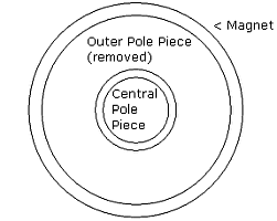
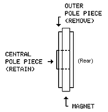
- The pendulum bob is the permanent magnet and central pole piece from a loudspeaker. The outer pole piece has been removed from the assembly. The outer pole piece normally surrounds the speaker voice coil; it looks like a large washer. (A light tap on a cold chisel will usually separate the magnet from the outer pole piece.) The absence of the outer pole piece forces the magnetic field outward. The Alternate Bob works as well.
| Bottom View | Side View |
|
|
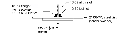
Alternate Magnetic Bob
If you don't have an old speaker to sacrifice.
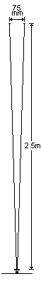
- In this example, the pendulum is 100 inches (2.5m) long, consisting of a 3" (75mm) threaded spacer (a small turnbuckle would work here) glued with epoxy to the bob/magnet assembly, plus two 96" (240cm) strands of dental floss. Its period is just over 3 seconds.
- The bob is suspended ~⅛" (3mm) directly above the stationary (blue) driver coil. The horizontal swing is about 12" (305mm).

The Driver Coil
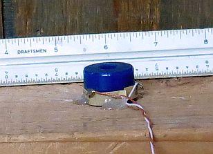
- The coil is from a 6-volt (DC) relay. The resistance of the coil is about 29 ohms. The center pole piece has been removed.
- Magnetizable objects (nails, etc) can disturb the pendulum's swing. These should be kept away from the coil and pendulum bob.
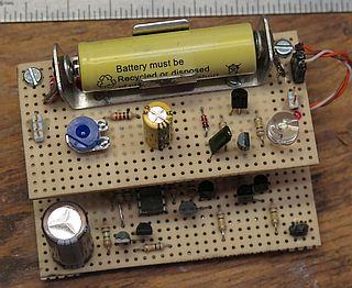
The Driver Electronics
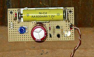
Figure 1

- The 29-ohm, 6-volt relay coil replaces the hand-wound coil described in the Williams article. I don't think this particular resistance value is critical to the functioning of the circuit. Likely any low-voltage relay coil would work, as would Williams's hand-wound coil. The central core (pole piece) must be removed from a relay coil for it to function as a pendulum driver.
- The red LED absorbs the inductive kickback induced in the coil each time the circuit fires; the LED will flash with each beat of the pendulum. The red LED is used in the circuit because it has the lowest forward voltage drop of all visible LED colors. "Ultrabright" makes the flashes easier to see.
- Rather than the transistors specified by Williams, I used the ones shown above from stock I had on hand. I suspect any small-signal PNP and NPN units would work.
- The transistor amplifier/trigger circuit has a very high gain (10,000+) and the original circuit was prone to breaking into oscillation at a very high rate (>100kHz), firing multiple times with each swing of the pendulum. To eliminate this, the 1000 µF capacitor shown in the original circuit (C2) was replaced with a .0022 µF unit. The circuit as shown delivers one and only one pulse per beat of the pendulum when properly adjusted.
- A 600 mAh NiCd cell and 1N5817 Schottky diode were added as shown to enable the pendulum to operate when the sun is not shining. Average current draw for the circuit (including the motor driver below) is 0.5 mA which suggests the pendulum should operate for at least a month without sunshine. The NiCd cell also provides a degree of voltage regulation which helps regularize the pendulum's period (useful in the following clock application). It's likely any NiCd or NiMH cell would work as well. The Schottky diode prevents reverse current flow in the solar cells.
- The two series-connected 1N914 diodes form a shunt regulator, limiting the charge on the capacitor to about 1 volt. This also serves to regularize the pendulum's period and may provide some temperature compensation.
- The 1000µF value of the storage capacitor (*) in Fig 1 is suggested for a 2.5m pendulum. Values for shorter pendulums are shown in the chart below.
- A variable series resistor and 1kΩ fixed resistor were added between the NiCd cell and the storage capacitor. The variable resistor is adjusted to optimize the firing rate of the trigger circuit. The adjustment is not difficult: The circuit should fire at a rate twice the pendulum's natural period, in other words, its pulse (or "beat") rate:
R ≈ T/2C
where R is the resistance (fixed plus variable) in ohms,
T is the period of the pendulum in seconds, and
C is the storage capacitor value in farads.
Adjustment: - Observe the red LED flashes.
Setting the resistance too high will cause the circuit to skip beats. Setting the resistance too low will cause the circuit to fire randomly. A setting half-way between the two points is near optimal.
- The variable resistor setting also has a slight influence on the pendulum's period. Setting the resistance higher will lower the pendulum's amplitude and lengthen the period. It will run a bit slower. Setting the resistance lower will have the opposite effect. This influence is subtle and should be noticed only when the pendulum's rate is compared to an accurate time source. (see: pendulum phase comparator)
More Notes
- The threaded spacer above the pendulum bob allows fine adjustment of the distance between the bob and the driver coil. The spacer is adjusted to the system's "sweet spot", the spacing that produces maximum swing amplitude.
- The heavy pendulum bob makes the as-built pendulum a reluctant self-starter; it needs a push to start.
- If you can't get the pendulum to run, flip the driver coil over or reverse the leads to the coil. The coil and permanent magnet on the bob must repel each other when the coil is energized.
- The pendulum and driver circuit shown were made with parts on hand. Other than the two transistors, it was all junk. Your results may vary, depending on what junk you have. Expect to do some experimenting.
More Junk
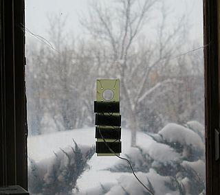
- This shows the solar array suspended in a south-facing window. The solar cells (and NiCd battery) are from trashed-out "garden lights". Under direct sunlight, each cell puts out 1 volt into an open circuit or 50 mA into a short circuit. With all four cells connected (in series-parallel) the NiCd would be over-charged, so only two of these cells are actually wired (as shown in Fig 1). The array, as presently connected (2 cells only), charges the battery at a 15-30 mA rate under direct sunlight (obviously not when this photo was taken). Another connection option would be to wire three or four of these in series and use the current regulator circuit shown in the box below.
- It looks like a single Futurelec SZGD3131 (2.2V/50mA) would substitute for the two 1-volt solar cells shown in Fig 1.
Clock Motor Driver
If you'd like to experiment with timekeeping and build a cool clock, the pendulum circuit can be used to drive an electric (battery) clock (1 pps impulse) motor. The result would be a mechanical/electric hybrid. [Solar-powered grandfather clock?] The electronics to do this are shown below. The circuit delivers alternating-polarity pulses to the motor winding. It has lots of transistors and resistors, but they're cheap:
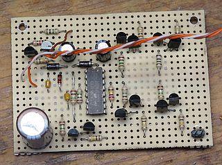
Figure 2

- Note that the driver circuit calls for two types of transistor: PNP type 2N2907A (or any small-signal equivalent), and NPN type 2N2222 (or any small-signal equivalent).
- The value of the resistor connected from pin 5 to pin 4 of the CD4027 J-K flip-flop sets the length of the motor pulses. The 270k value shown generates pulses of around 25 mS duration, which I think will work for the majority of single-cell (1.5-volt) clock motors; "high-torque" motors may require a longer pulse. If the motor fails to "tick" correctly, add a second .1 µF capacitor from pin 4 to ground.
- The two 1N5817 Schottky rectifiers shown in the circuit operate as a charge pump to charge the 100µF capacitor connected to pin 16 of the CD4027 - to about 2.4 volts when the Ni-Cd cell is at 1.4 volts, and 2 volts when the Ni-Cd is at 1.2 volts. This provides power for the chip. Yes, the CD4027 will operate on 2 volts in this not very demanding circuit.
- It will require 3 or 4 pulses from the pendulum to fully charge the +2.4-volt power rail on start-up.
Pendulum Driver Mated to Motor Driver
- The pendulum should be about a meter in length. This length produces a period of two seconds, or one pulse per second. As with any pendulum clock, the pendulum's length (and/or center of mass) should be adjusted until the clock runs at the right speed to always tell the correct time. It will likely end up being somewhat longer than 1 meter, depending on where the center of mass lies on its length.
- The value of the storage capacitor in Fig 1 should be changed to 680µF or thereabouts.
Solar-Powered Hybrid Mechanical-Electric Clock

- The dental floss has been replaced with 1/4" rigid aluminum tubing [6061 alloy], with a 1/8" threaded brass rod screwed into the lower end. The total length is 40.5" (1028mm) including the original 3" threaded spacer at the bottom. The suspension spring at the top adds another 1" (25mm).

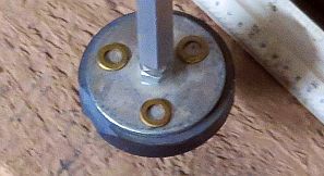
- This tab allows the coil to be precisely centered under the pendulum bob. The adjustment is made with the pendulum at rest. The screw, washers and tab are non-magnetic. A plastic screwdriver was used to tighten the screw.

- The support is made with bits and pieces of scrap hardware. The suspension spring hangs between two closely-spaced (<0.2mm) cylindrical posts which pinch the spring so as to restrict its movement. The posts' height effectively sets the height of the pendulum's pivot point, and thus its length, independent of the bob/coil spacing. The spring is from a defunct tape measure.
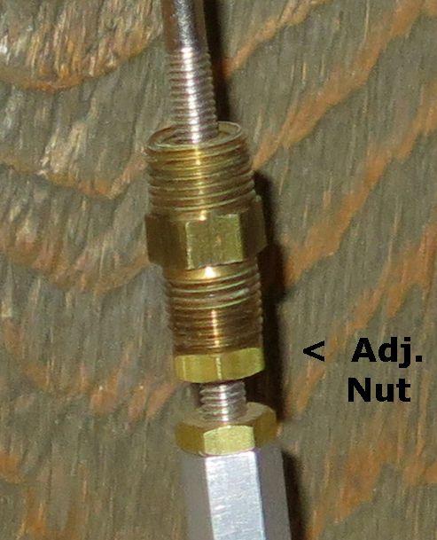
- This is the fine adjustment nut on the pendulum shaft. The adjustment raises or lowers a sliding weight (brass pipe fitting) above it, which raises or lowers the pendulum's center of mass. This adjustment is also independent of bob/coil spacing. One turn of the nut produces a rate change of roughly 10 seconds per day.
- Three thin brass washers placed on the bob were needed to slow the pendulum just enough to bring its rate within range of the fine-adjust nut.
Disruptive Kitten
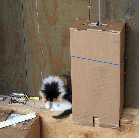
I had to provide a shield to protect the pendulum from a very curious and playful kitten, seen here chewing on the wire that connects the electronics to the clock motor..
--
Schematics produced with DCCAD.
Top of page.
Parts
| 2N2222 (PN2222): | Futurlec/PN2222 |
| 2N2907A (PN2907A): | Futurlec/PN2907A |
| CD4027B: | Futurlec/CD4027 |
| Resistors, capacitors, diodes, LEDs: | Futurlec/components |
| Solar cells: | Futurlec/SZGD6535 |
Futurlec is cheap, but they're slow. Allow 2-3 weeks for delivery.
|
|
 |
