Convert ITT 6-Button Key Set (K-500) to Single-Line Operation
Excellent (but obsolete) telephone gets a new life as a single-line set.
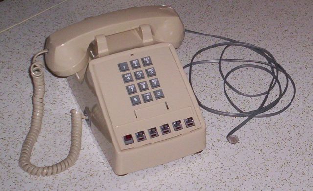
The highly functional 6-button key telephone was a familiar fixture in small offices and businesses for many years. In those years before digital electronics, the sets' functionality came at the cost of lots of unseen on-premise hardware support - a 25-pair (50-conductor) cable connected each and every phone in the office, and a large key support unit (KSU) and its power supply hung on a backroom wall somewhere. As these systems were replaced, the key sets, unable to function without the support structure, became useless. If you happen to have one of these old phones, the following conversion could rescue it from a landfill and allow it to be used as a free-standing set on a standard 2-wire phone line. The keys (buttons) become non-functional.
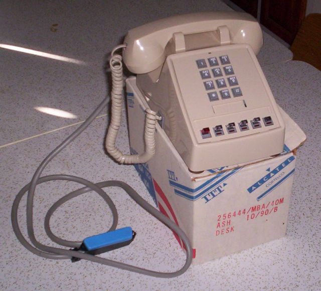
The conversion shown here is on a later model (1990), new-out-of-the-box ITT K-500 with an "IC" DTMF dial pad. Unfortunately, the modifications shown don't work on older models with "discrete" DTMF dial pads (let alone rotary dial models). There is no reason an older model couldn't be converted, however. With the information shown, you just might be able to pull it off..
The 6-button set before conversion
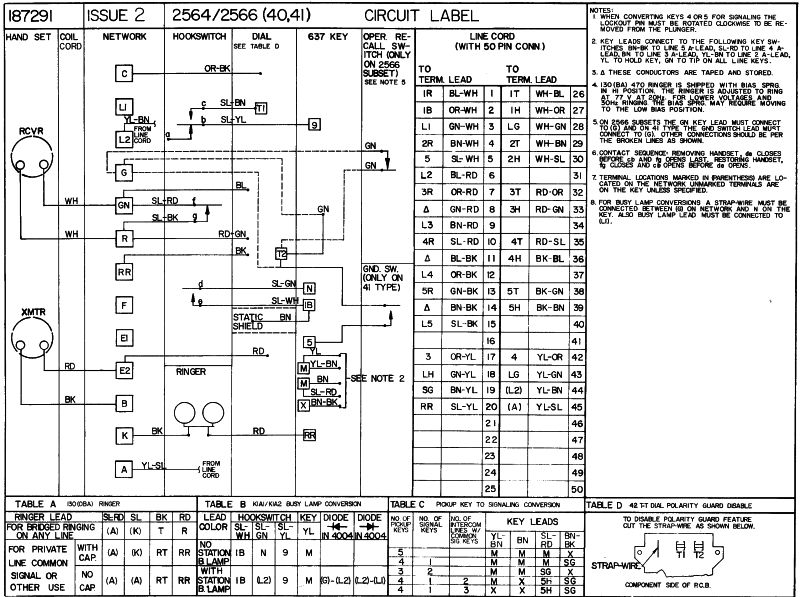
Here's the original wiring diagram
Conversion Steps
Converts 6-button key set with "IC" DTMF dial to single-line (2-wire) operation
- Remove the 25-pr line cord and all of its wires from the 6-button key assembly;
- On the NETWORK, connect (or verify connections) as follows:
- G - NC
- L2 - SL/YL (hookswitch), RD (2-wire line cord)
- L1 - SL/GR (hookswitch), BK (ringer), GR (2-wire line cord)
- RR - BK (dial)
- R -RD/GN (dial), SL/BK (hookswitch), WH (handset)
- E1 - NC
- C - OR/BK (dial)
- B - BK (handset)
- E2 -RD (handset), RD (dial)
- F - NC
- GN - BU (dial), WH (handset), SL/RD (hookswitch)
[Ringers come in two types, single coil (2 wires) and dual coil (4 wires).]
- Connect (or verify) the wires from a single coil RINGER as follows:
- RD to K (network)
- BK to L1 (network)
- A (network) to L2 (network) (Construct a jumper from a couple of unused key switch wires.)
- Connect (or verify) the wires from a dual coil RINGER as follows:
- RD to L2,
- BK to L1
- SL/RD to A (network)
- SL to K (network)
- On the DIAL connect (or verify connections) as follows:
- Right terminal (as viewed from the front of the phone) - SL/BN (hookswitch)
- Left terminal (as viewed from the front of the phone) - SL/WH (hookswitch)
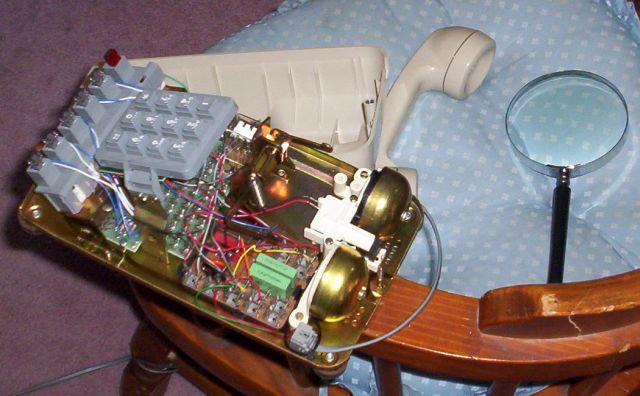
Here's the interior of the set
The NETWORK is in the foreground
The set after conversion