Electronic Construction Project
Portable Photo Relay
Relay applies 120VAC power to load when dark.
|
Figure 1
Schematic

| * BIAS CONTROL: Increasing resistance biases circuit towards "ON" state. This control is optional. If the bias control is not used, replace with a short. (The photo relay can also be biased by partially blocking the light falling on the LDR.) | |
| ** SAFETY POLARITY CHECK: Ground terminal for polarity check. If neon lamp lights, polarity is correct. If neon does not light, reverse input plug. Read the safety considerations below. |
|
| *** See load addendum below. |
Parts for Figure 1
| TRANSFORMER | 115V/6Vx2, BV020-5417.0 (Pulse), Digikey cat# 567-1007 |
| LDR | Light Dependent Resistor, All Electronics cat# PRE-12 (or similar) |
| 7555 | CMOS timer, LMC555CN (Nat. Semiconductor), Digikey cat# LMC555CN |
| SS RLY | 2 Amp Solid-State Relay, G3MC-202PL DC5 (Omron), Mouser cat# 653-G3MC-202PL-DC5 |
| POT | 1k ohm, 9mm, Digikey 3309-102 (Optional. If not used, replace with short.) |
| NE-2 | Neon Lamp, Mouser cat# 606-A1A |
| RECEPTICAL | 2-cond, snap-in, Digikey Q281 |
| CASE | Plastic, 4.5" x 2.75" x 1" (11.4cm x 7cm x 2.5cm) |
| MISC | Small parts as shown on schematic |
Digikey Mouser Electronics All Electronics
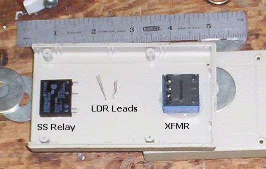
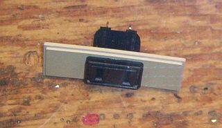
Construction Started
All parts are secured to the case with silicone rubber sealant (RTV).
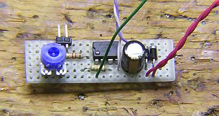
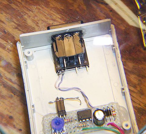
Circuit Board Completed
Most of the small components for the project are mounted on the board.
The 2-pin header will connect to the LDR.
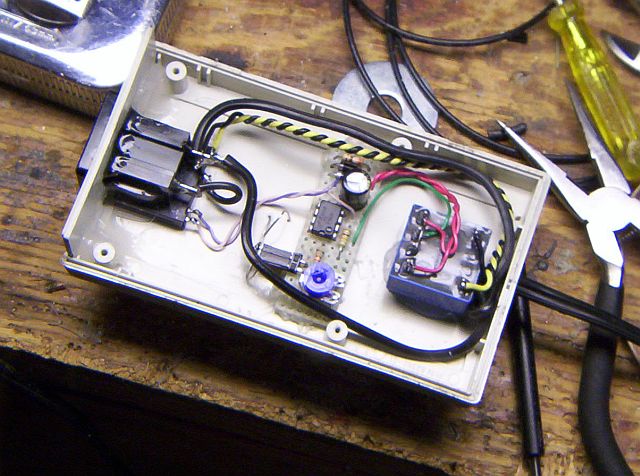
Circuit Board Mounted in Case
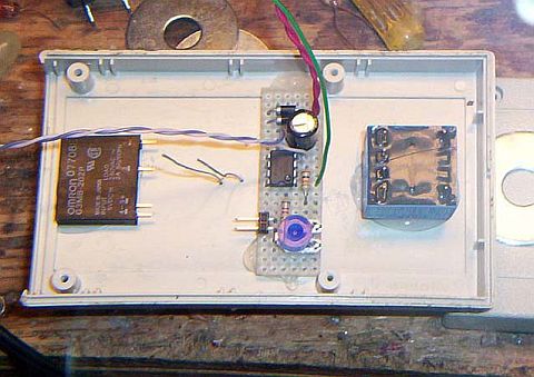
Wired
Output Receptical
Installed in Case
Input Line Cord and Transformer Primary Wiring Installed
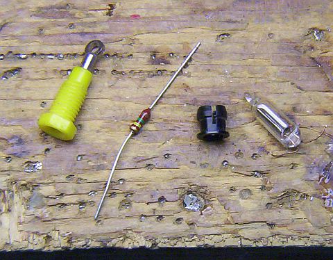
Polarity Check Parts
Tip jack (this will be the grounding terminal), 150k resistor, LED mounting sleave, NE-2.
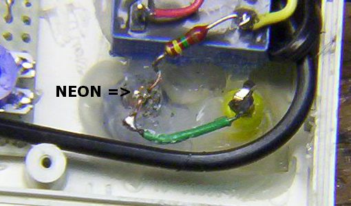
Neon Lamp and Ground Terminal Installed
in an ocean of RTV.
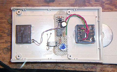
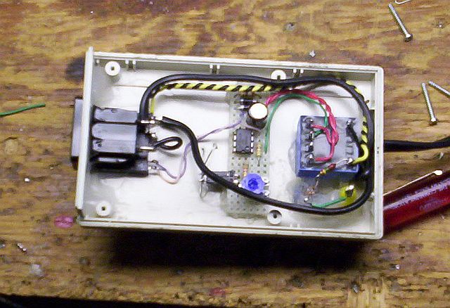
Completed Project - Internal
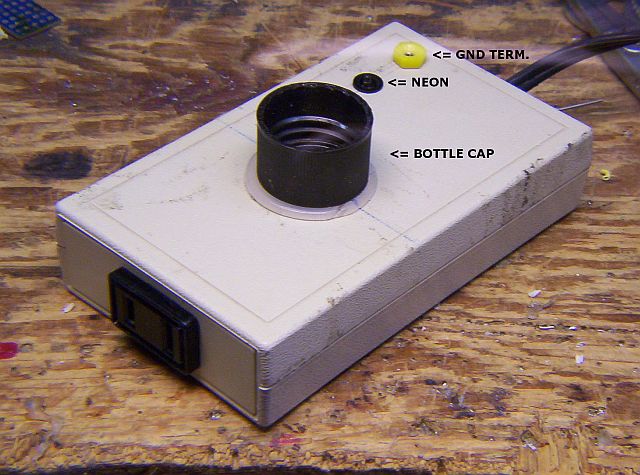
Completed Project - External
Yes, that's a bottle cap. It protects the LDR and gives it directionality.
Close-up of LDR
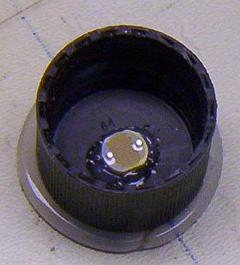
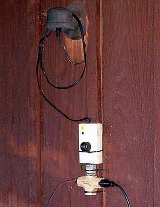
Photo Relay in Service
This is an outside location protected from the weather under an eve.
- Safety Considerations -
This circuit, when constructed using the certified, hi-pot tested devices specified in the parts list (transformer and SS relay) is capable of very high electrical isolation. However, the Photo Relay shown constructed on this page is a self-contained portable (temporary) version. As such, several things should be kept in mind when using it:
- The Photo Relay must be protected from the weather and other wet conditions. (See below.)
- A polarity check should be performed before placing the Photo Relay in service. This will assure that both output conductors will be de-energized when the device is in the "OFF" state. (The polarity check is not applicable if the Relay is constructed for 240VAC use. See below.)
- Disconnect the Photo Relay from the power source before working on any appliance or wiring controlled by the device.
Variation #1: Build a 240VAC Version
Single-Pole:
The photo relay can be constructed as a 240VAC single-pole version by substituting a 240-volt transformer for the transformer shown in the Figure 1 parts list above and deleting the 150k resistor and neon lamp. No other changes are required. The single-pole version is appropriate for portable (temporary) service only if the relay will be connected to a 240-volt fully floating and balanced branch circuit protected by a ground-fault circuit interrupter (GFCI).
| TRANSFORMER | 230V/6Vx2, BV020-5388.0 (Pulse), Digikey 567-1022 |
Two-Pole:
A two-pole version is shown in Figure 2. Use this configuration if the photo relay will be connected to a non-GFCI protected 240-volt branch circuit (or if the circuit breaker type is unknown).
Figure 2
Schematic - 240VAC, 2-Pole Version
| * BIAS CONTROL: Increasing resistance biases circuit towards "ON" state. This control is optional. If the bias control is not used, replace with a short. (The photo relay can also be biased by partially blocking the light falling on the LDR.) | |
| *** See load addendum below. |
Parts for Figure 2
| TRANSFORMER | 230V/6Vx2, BV020-5388.0 (Pulse), Digikey 567-1022 |
| LDR | Light Dependent Resistor, All Electronics PRE-12 (or similar) |
| 7555 | CMOS timer, LMC555CN (Nat. Semiconductor), Digikey cat# LMC555CN |
| SS RLY (2) | 2 Amp Solid-State Relay, G3MC-202PL DC5 (Omron), Mouser cat# 653-G3MC-202PL-DC5 |
| POT | 1k ohm, 9mm, Digikey 3309-102 (Optional. If not used, replace with short.) |
| RECEPTICAL | |
| CASE | |
| MISC | Small parts as shown on schematic |
Variation #2: Build a Remote/Weather-Proof Version
The light sensor (LDR) can be remoted with low-voltage wiring to make a "weather-proof" version of the circuit as shown in Figure 3. Encapsulate the LDR in a transparent or translucent water-tight outside enclosure; install the remainder of the circuit at a weather-protected inside location.
Figure 3
Remote LDR
Variation #3: Build a High-Current Version
For higher current applications, the solid-state G3MC series relay/s and 390-ohm resistor/s specified can be replaced with a high-current solid-state relay (or relays) such as the Omron G3NA-2xxB-DC5-24 series (up to 90 amps) or Crydom H12WD series (up to 125 amps). Replace the 390-ohm resistor/s with a short.
Alternately, the Figure 1 circuit can be used to drive (pilot) a 120/240VAC electromechanical relay or contactor, as shown in Figure 4.
Figure 4
Photo relay drives elecromechanical relay.

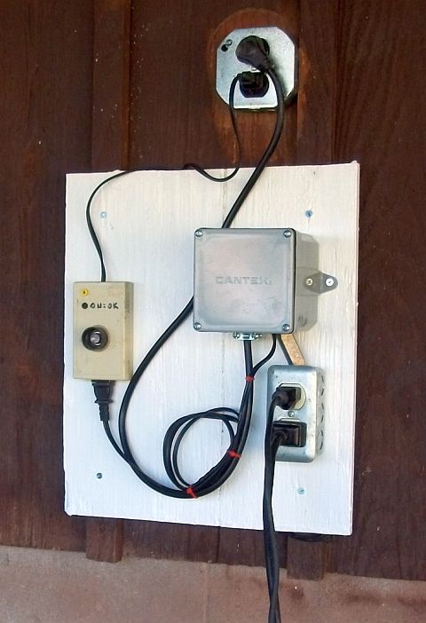
Installed Example
The electromechanical relay is in the gray box.
Variation #4: Build a Off-When-Dark Version
The relay circuit can be modified to de-energize the load when it gets dark. The circuit remains the same in all respects except that the wiring of the SS relay and its associated 390-ohm resistor are changed as shown in Figure 5. Note that operation of the BIAS control changes.
Figure 5
Schematic - Off-When-Dark Modification.
| * BIAS CONTROL: Increasing resistance biases circuit towards "OFF" state. This control is optional. If the bias control will not be used, replace with a short. (The photo relay can also be biased by partially blocking the light falling on the LDR.) |
Addendum: Solid-State Relay Loads
Minimum Load
Unlike an electromechanical relay, a solid state relay will not completely switch to the "OFF" state into a high resistance (i.e., low wattage) load or open circuit. The maximum resistance the Omron SS relay can tolerate is about 1200 ohms, equivalent to 12 watts of non-incandescent resistive load (0.1 amp) at 120 volts. For an incandescent load, minimum equivalent load is about two watts (the cold resistance of a 2-watt incandescent lamp is less than 1200 ohms). Interestingly, for a magnetic load (motor, relay, transformer, etc.), the minimum load is virtually zero watts, since AC magnetic devices register very low resistance when de-energized. In other words, the minimum load depends on the type of load:
| Load Type | Minimum ON wattage for this load type | Typical OFF Resistance at this wattage |
| Resistive | 12 watts (24 watts @ 240 volts) | 1200 ohms (2400 ohms @ 240 volts) |
| Incandescent | 2 watts (4 watts @ 240 volts) | <1200 ohms (<2400 ohms @ 240 volts) |
| Magnetic | <1 watt | <200 ohms |
Special Case - LED Loads
An interesting effect can be seen when the relay is connected to a string of LED decorative lights. These srings consist of a rectifier and 35 or so LEDs connected in series (70 LEDs for 240-volt strings). Since LEDs are high-speed non-linear devices, they switch off each time the drive voltage drops below a threshold of 2-3 volts per LED. This occurs in normal operation twice during each AC cycle. The LEDs appear to be glowing continuously but in fact are flashing at twice the frequency of the AC power line.
The minimum load/maximum resistance requirement comes into play when the SS relay switches to the "OFF" state. Each time the string voltage drops below the LEDs' threshold voltage, the string looks like an open circuit to the relay. The relay tries to supply current to the LED string and the string voltage rises to the threshold. The result is a series of clipped-at-the-threshold pulses being fed to the LEDs at 2x the line frequency. The visible result is, instead of going dark, the string glows dimly. This occurs regardless of the number of LED strings connected to the relay.
If this is not acceptable, the remedy is simple: Provide at least 2 watts of incandescent load in addition to the LED load. A single 2-watt (or larger) 120-volt lamp (4-watt at 240 volts), or string of lamps, connected in parallel with the LED string, will completely eliminate the effect. Alternately, some sort of magnetic load can be used, a doorbell transformer or transformer-powered (non-switcher) wall wart power adapter, for example. (It's not necessary to connect the wall wart to its load.)
If your only concern is to eliminate the dim glow of the LEDs when the Photo Relay is off, a relatively high-value resistor can be used. While this will not allow the SS relay to completely switch to the "OFF" state, it will lower the output voltage enough to extinguish the LED string. Probably the most practical place for this resistor is across the terminals of the Photo Relay's output load receptical, as shown in Figure 6. The presence of this resistor will not affect operation of the relay with other load types.
Figure 6
Optional load resistor when Relay is to be used with LED strings.
(use 100k, 1w for 240VAC)
Special Case - Surge Current and Switching Power Supplies
The specified SS relay has a surge current rating of 30 amps. While this is perfectly adequate for most load situations, including fluorescent lamps and motors, there is one type of load where it may not be: non-power factor corrected (PFC) switching power supplies. These supplies typically operate directly from the AC line with a full-wave rectifier followed by a large-value ripple filtering capacitor. This capacitor represents a virtual short-circuit to the line at the moment power is applied and 100 amps or more may flow during the first cycle or two after turn-on, greatly exceeding the SS relay's surge rating.
A well-designed switching supply will include power factor correction or an inrush current limiter, also known as a Negative Temperature Coefficient (NTC) thermistor, which prevents this happening. If you are unsure of your switching power supply you may want to include one in the Photo Relay as a precaution. The current limiter is connected, as in the above example, at the rear of the load receptical. The inrush current limiter should be connected between the SS relay and the load as shown in Figure 7. The current limiter specified will limit the inrush current to well below the SS relay's surge current rating. The current limiter will run warm during normal loaded operation.
Figure 7
Optional inrush current limiter, needed only when the AC load is a non-PFC switching power supply.
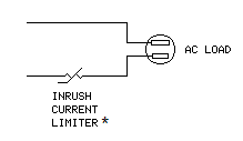
*Mouser 527-CL80
Schematics produced with DCCAD.
