Circuit Randomly and Independently Flashes (Blinks, Twinkles) Series-Connected Ultra-Bright LEDs
Shunt LED Flasher
I didn't think this could be done until I thought about it awhile.
Background
This little circuit is used to randomly flash some of the ultra-bright LEDs on this LED-illuminated star. The 40 blue and white LEDs are series-connected and powered by a current-regulated, high-voltage power supply. The current is regulated at 310 milliamps.
So how do you independently flash 'em?
The Circuit
The circuit is connected across (parallel with) each ultra-bright LED you want to flash. The red LED flasher flashes at around 2 Hz. When the red flasher is ON the transistor is switched ON, allowing current to flow through resistor R. The resistor shunts current from the ultra-bright LED, causing it to go OFF. The resistor value is selected to lower the voltage across the ultra-bright LED to about 2.25 volts. At this voltage, green, blue or white ultra-brights do not emit light. Red, amber and yellow ultra-brights require a lower turn-off voltage and a slightly different circuit with an added component. The circuits are shown below. The resistor values shown are for 310 mA LED current. Values for 350 and 700 mA are shown in the charts. Values for other LED currents are easily calculated.
Green/Blue/White Circuit (2.25 volt turn-off)
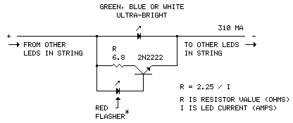
| LED Current | Shunt Resistor R | Series Diode |
| 310 mA (as shown) | 6.8 Ω | NO |
| 350 mA | 6.2 Ω | NO |
| 700 mA | 3.3 Ω | NO |
Red/Amber/Yellow Circuit (1.75 volt turn-off)
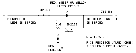
| LED Current | Shunt Resistor R | Series Diode |
| 310 mA (as shown) | 5.6 Ω | YES |
| 350 mA | 5.1 Ω | YES |
| 700 mA | 2.4 Ω | YES |
Notes:
- The shunt circuit is designed be used in a series-connected, current-regulated multiple ultra-bright LED string.
- The circuit flashes only the LED it's paralleled with.
- For multiple flashing LEDs, duplicate the circuit and connect it across each LED you want to flash; as many as you want.
- The flasher circuits are asynchronous; each flasher operates independently (see below for synchronous flash).
- The shunt resistor will run warm. 1-watt, metal film flameproof type recommended.
- Cover the red LED flasher* if you don't want it to be seen (duh).
Parts sources below.
Variations on the Basic Circuit
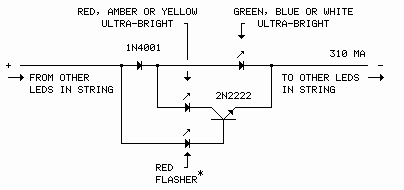
Alternating Colors
This circuit alternates between lighting a white, blue or green ultra-bright and a red, amber or yellow ultra-bright. The rate is the same, about 2 Hz.
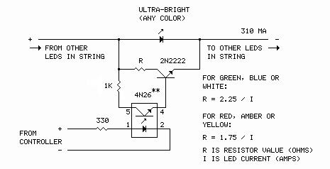
Remote Control
This circuit would be useful for more elaborate displays driven by a microcontroller. 5 volts DC on the control line extinguishes the ultra-bright.
Flash Multiple Ultra-Brights Simultaneously
Up to six blue/white/green or seven red/amber/yellow or any combination of mixed colors can be flashed together.
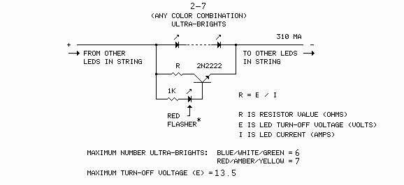
The value of the shunt resistor (R) is determined as follows:
- Add the turn-off voltages of the individual LEDs to arrive at the total turn-off voltage (E). Blue, white and green ultra-brights turn-off at 2.25 volts; red, amber and yellow ultra-brights turn-off at 1.75 volts. Colors can be mixed.
- Plug the total turn-off voltage into this formula:
R = E / I (R is the value of the shunt resistor, E is the total turn-off voltage and I is the LED current.) - Do not exceed 13.5 volts total turn-off voltage. Doing so may exceed the safe operating voltage limit of the red LED flasher.* For example, 3 blues and 4 reds [E = 13.75] would exceed the limit, while 6 blues [E = 13.5] would not.
Note: 2-watt shunt resistor (R) recommended for multiple flasher.
Parts:
| *RED LED FLASHER | Flashing 5mm round red LED, Futurlec LED5RFL (or similar) |
| 2N2222 | NPN general purpose transistor, Futurlec MPS2222A (or similar) |
| DIODE | 1-amp, 50-volt general purpose rectifier diode, Futurlec 1N4001 (or similar) |
| RESISTOR (R) | 1-watt, 5% metal film, flameproof, Digikey cat# PPC[value]W-1CT-ND (single flasher) |
| 2-watt, 5% metal film, flameproof, Digikey cat# PPC[value]W-2CT-ND (multiple flasher) | |
| RESISTOR (1K) | 1/4-watt, 5% carbon film, Futurlec R001K14W or Digi-key 1.0KQBK-ND (or similar) |
| **OPTO-ISOLATOR | 6-Pin Phototransistor Optocoupler, Futurlec 4N26 (or similar) |
Futurlec Digikey
Note: Futurlec is pretty slow (but they're cheap). Allow 2-3 weeks for delivery.
Total cost per circuit: about 54 cents US ($0.54) from suggested vendors, not including shipping.
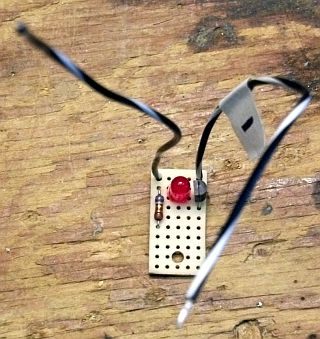
Photo
One of the ten shunt flasher circuits built for the LED-Illuminated Star. The negative lead (-) is connected to the cathode of the ultra-bright to be flashed, the other lead to the anode. Because they would be installed outside, the circuits were waterproofed with RTV.
Flashers in Action
Don't let the size of this little image fool you. The star is 18 feet (5.5m) tall.
Schematics produced with DCCAD.