Old Junk Given New Life
PIR Motion Sensor Rebuild Project
This article is a breakout from a longer article: Long-Range Wireless Gate Annunciator.
A microwave motion sensor (see) proved ultimately to be a better choice for the application,
but you might find this information useful in your application.
Max Carter
I had 3 defunct motion sensors, removed from motion-operated floodlights, all Heath/Zenith units, a model that seems to be particularly unreliable. Given the poor reliability of these sensors and the need to troubleshot a bad unit before even attempting to adapt it to my purpose (here), I decided not to try and rehabilitate the sensor electronics and returned instead to first principles. I would retain the enclosure and mount and build the sensor electronics up from scratch.
Heath/Zenith Motion Sensor

Original electronics and Fresnel lens removed - outer case and clear plastic horn retained.

Brittle and crumbling after years in the sun, the Fresnel lens could not be reused, so I ordered a new lens.
($1.20 from 3Dlens.com, #5058, note #5059 would likely work with some trimming.)

Also, not wanting to trust the PIR sensor on the original Heath/Zenith electronics board, ordered in a new PIR sensor.
($1.90 from Futurlec, #PIR_D203S)

PIR Sensor Interface Electronics
A pretty good explanation of how a Passive (or Pyroelectric) InfraRed (PIR) sensor works can be found on Wikipedia. The main takeaway is that the useful output of the PIR sensor is a tiny AC signal superimposed on a DC voltage. The detector circuit reacts to abrupt changes in the sensor's output, in other words, to the AC component produced by moving objects. The (usually relatively large) DC component is produced by steady or slowly varying background IR radiation from objects and terrain, fixed artificial heat sources or very slowly moving objects. From information in the Wikipedia article, the data sheet for the PIR sensor, snippets of circuitry found on several web pages, and some experimenting, I was able to piece together and build the amplifier/differentiator circuit shown in Figure 1.
Figure 1

The output of the PIR sensor appears on pin S and is directly coupled to the first amplifier stage (U1a). The first stage amplifies the desired AC signal (~2-20 Hz) with a voltage gain of about 20. The non-varying and slowly varying (<1/10 Hz) background level is not amplified. The first stage is coupled to the second (U1b) through the 22 µF capacitor. Only the AC component of the signal is passed by the capacitor. The voltage gain of the second stage is variable via the SENS control from 125 to about 350, for a total gain of 2500-7,000 (68-77 dB).
The circuit was developed and tested on the bench, but some issues could not be known until the sensor was in service.*
The output of U1b is directly coupled to U1c and U1d, which, with two diodes, form a voltage comparator and full-wave rectifier. When the output of the second stage amplifier reaches a level of about 1 volt peak-to-peak, one or both of the diodes conduct, charging the 150 µF capacitor and turning on the NPN transistor (2N2222) and the PNP transistor (2N2907). The charge on the capacitor maintains the output in the ON state for a few seconds after the moving object has passed. **The output is HIGH [12V @ 500 mA] when motion is sensed. The output can be used to directly power devices [LEDs, audible alarms, etc.] or to drive a relay.
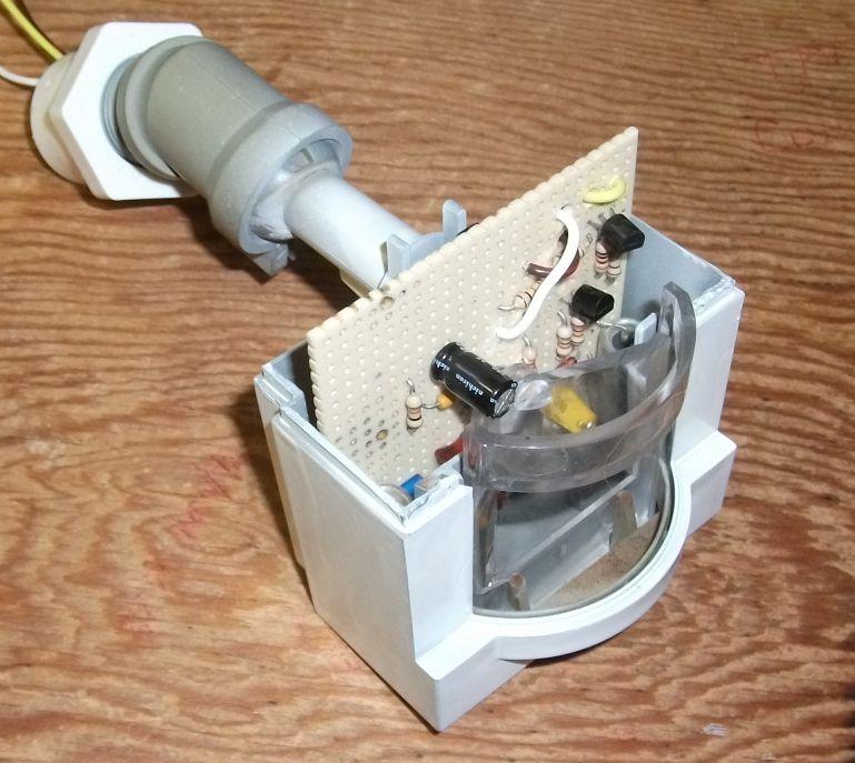
The new interface circuit was built on a piece of perforated circuit board with the same dimensions as the original detector board, with the PIR sensor placed at the same physical location at the center of the board.
PIR Interface Board
The PIR sensor is the only newly purchased device on the board. The balance of the circuit was built with parts on hand, mostly unused old stock. Some of the capacitors had been cannibalized from equipment.

The new board was installed in the original case in place of the original detector board. The original plastic horn was reinstalled, along with the new Fresnel lens, and the case sealed up with RTV. A hole in the bottom of the case allows access to the SENS control.
I assume the function of the horn is to help focus IR radiation arriving from the front onto the sensor and maybe to shield the sensor from the tiny amount of heat generated by the electronics board.

Completed Motion Sensor

Related Articles
Long-Range Wireless Gate Annunciator
HB100 Microwave Motion Sensor
