This page describes a different way to detect a vehicle or pedestrian entering through the gate: the microwave motion sensor. While the installed PIR sensor works 99% of the time, there are occasions when it doesn't, usually during precipitation events (heavy snowfall, rain, drizzle). This gave me an incentive to investigate another interesting approach. The device described uses the HB100 microwave motion sensor. These are incredibly cheap: available on eBay for as little as $3. A microwave motion sensor differs from a PIR sensor in that it's an active device. Whereas the PIR sensor monitors ambient (IR) radiation impinging on the device, the microwave sensor radiates a low-power microwave beam and monitors the signal reflected from objects.
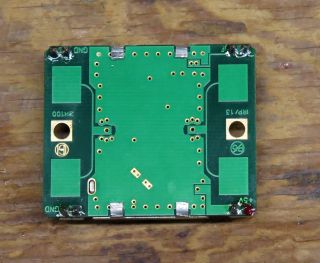
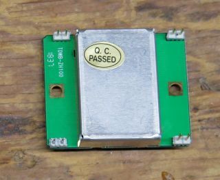
HB100
| Antenna Side | Other Side |
 | 
|
| Note installed header pins. |
The HB100 consists of a 10.525 GHz dielectric resonator oscillator (DRO), transmit antenna, receive antenna and Schottky diode receive mixer/detector. If an object within range is moving relative to the sensor, the reflected signal will differ slightly in frequency from the transmitted signal (the "Doppler effect"). The frequency shift depends directly on the target's speed as seen by the sensor - the greater the relative speed, the greater the shift. The received signal is mixed with a sample of the transmitted signal to derive a difference signal. The difference signal appears at the sensor's IF output pin.
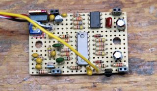
IF Amplifier/Filter/Rectifier
The sensor requires an amplifier/filter/rectifier to complete the system. Figure 1 shows the circuit, derived mostly from this application note. It consists of a sample-and-hold input stage, variable gain filter/amplifier, full-wave rectifier and output buffer transistor.
Figure 1
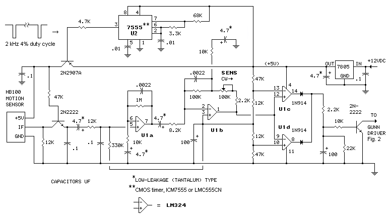
The motion sensor is operated in pulse mode to minimize power consumption, important when the power supply is a battery. The 7555 (U2), a CMOS version of the 555, generates 20 µS pulses at 0.5 mS intervals (2 kHz 4% duty cycle). The sensor radiates only when the output pin (3) of U2 is low. This results in a 25:1 reduction in average power consumed by the sensor module, and a reduction (by 14 dB) in average radiated power. After adding in the power consumed by U2, average current draw is about 5 mA, compared to 50 mA the sensor would draw in continuous mode. (See CW circuit.)
Pulse mode could be thought of as a form of spread-spectrum, a technique used in wireless communications systems to minimize interference. The synchronous sample-and-hold input to the IF amplifier operates as a 'matched filter' to de-spread the received signal, making it appear to the amplifier/filter as a continuous, low-frequency signal. This compensates for the reduced transmitter power and may provide some interference rejection. Note that the sample-hold transistor (2N2222) operates in reverse active mode during part of the sample cycle. [Google: "bjt reverse active mode"]
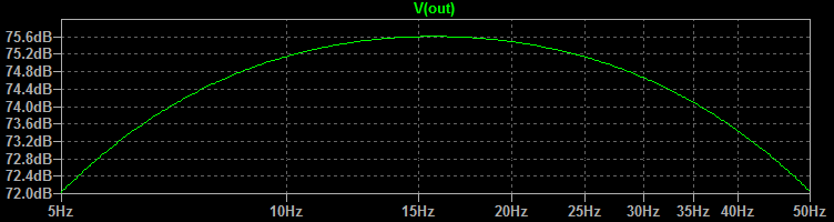
The IF signal from the sensor is amplified and filtered by opamps U1a and U1b. Gain can be adjusted from about 1000 to 10,000 (~60-80 dB). Frequency response is ~5-50 Hz, making the sensor most sensitive to speeds in the range of 0.15 to 1.5 MPH (0.25-2.5 km/h), walking speed. (For more on the speed range issue, see 'Lessons Learned' below.) The output of U1b is fed to U1c and U1d. When the signal exceeds 1 volt peak-to-peak amplitude, one or both 1N914 diodes conduct, charging the 100 µF capacitor and turning on the NPN output transistor. The output is pulled to ground when a moving object is detected.
IF Amplifier Gain vs Frequency
| IF amplifier as-built | Mated to HB100 |
 Note the four 2-pin headers. These accept the pins on the HB100. | 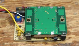 |
| Installed in weather-tight box | Mounted on the gate post opposite the PIR sensor |
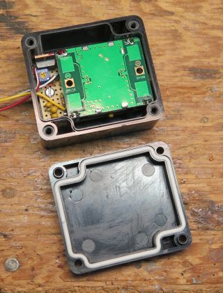 | 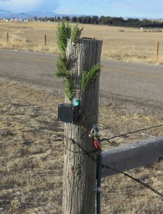 |
See the original article for complete details of the remote sensor installation.
Update: Lessons Learned
- The sensor should be mounted horizontally (as shown in the photos above) for best performance. In this position, the sensor radiates a horizontally polarized signal.
- Mount the sensor 30-36" (75-90cm) above the roadway level. Mounting any higher may allow some small cars to pass without detection.
- To avoid nuisance trips, the sensitivity control [SENS] should be set no higher than what is necessary for reliable detection. A setting near the low end of its range will likely be optimal for detecting vehicles in an outdoor environment.*
- Beware of nearby metallic objects moving in the wind. A bouncing strand of barbed wire on the rear side of the sensor caused false alarms until it was secured.
- Installed at its initial location, the sensor was exquisitely sensitive to pedestrian motion, but was virtually blind to vehicle motion! Why? I soon learned that the sensor was discriminating against the speed of the targets' motion. As explained above, the IF amplifier discriminates against speeds above about 1.5 MPH. The fix was to relocate the sensor so as to place its axis at a less acute angle to the direction of travel. The angle was increased from about 10° to about 80°. See illustration below:
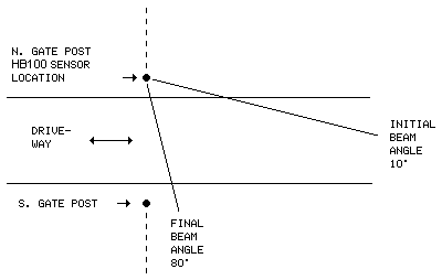
The sensor "sees" the target's speed multiplied by the cosine of the angle between the target's moving direction and the axis of the module (see app note). At the new angle (80°), the ratio of actual speed to apparent speed is increased by a factor of about 5.7 [cos10/cos80] over the original angle, an improvement of nearly six-fold. Given the ±45° width of the sensor's beam, vehicles passing through the gate travelling at almost any speed now fall within range of the IF amplifier's frequency response and are easily detected.
Note that the ability to discriminate based on the target's speed would also be useful in detecting pedestrians while ignoring vehicles. In that case, the original 10° beam angle might be near optimal.
PIR and Microwave Sensor Compared
*Choosing Cars over Critters
As it turns out, the microwave motion sensor out-performs the PIR sensor in this application. It reliably detects moving vehicles and animals during damp weather events (rain/drizzle) when the PIR sensor is not effective. I took advantage of the microwave sensor's uniform performance and lowered its sensitivity setting to a point where cars are detected but critters are not. The reason? Deer. Herds tend to move in single file and a herd of 10 travelling through the gate might trip the system 5-10 times as they come through (annoying). Yes, by lowering the sensor's sensitivity I am choosing to ignore pedestrians (human critters) but, this being a rural location, visitors very rarely if ever arrive on foot. The ability to detect pedestrians can be restored to the sensor if needed simply by readjusting the sensitivity setting upward.
Schematics produced with DCCAD.
Parts
| HB100 | - | Open Impulse I ordered two, got two, but one was dead on arrival. You takes your chances. Google "HB100" |
| IF Amplifier | - | All components were obtained from Futurlec. Cheap but slow (2-3 weeks). |
| Weather-tight Box | - | Amazon (also has HB100) |
Related Articles
Long-Range Wireless Gate Annunciator
Temperature-Compensated Solar Battery Charger
PIR-Sensor Rebuild Project
Beep/Siren Power Amplifier