LP Filter/Schmitt Trigger
|
The phase information is conveyed in the duty cycle of the comparator output pulses, as shown in the figure below. The first line shows the pulses as they come from the comparator. The second line shows the pulses after integration by the LP filter (comprised of the 10k series resistor and .1 uF feedback capacitor). The third line shows the logical output from the Schmitt trigger (the two series inverter gates and feedback resistor). The fourth line shows the "delayed" logical output (the delayed output is used for the computer-interfaced version only). The delayed LP filter/Schmitt trigger circuit is identical in all respects, except for substitution of a lower-value feedback resistor (22k) in the feedback loop. The lower value resistor results in a wider hysteresis band, which generates a delay of about 45 degrees. Not to scale. 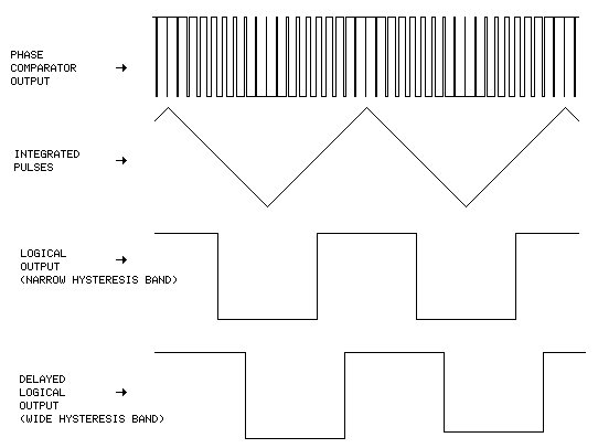 |
Read the Article:
WWVB-Based Precision Frequency Comparator
