Thanks to the generosity of a friend of a friend of a friend, I've been given a used rubidium (Rb) frequency standard. It's a fully functional unit that had been in continuous service at a cell site for 8-10 years.
Rubidium Frequency Standard
Lucent RFG-M-RB

A rubidium standard, or rubidium atomic clock, normally can be considered accurate to within a few parts in 1011 (stratum II), but will tend to drift a small amount over time (I read). I was curious to know if the unit had retained its accuracy over the years, so embarked on an effort to determine that.
The time honored method for checking a frequency standard is to do a direct phase comparison to a more-accurate source using a 2-channel oscilloscope. The more-accurate source in this case would have to be a cesium-beam clock or Rb stratum-I clock disciplined through the GPS system. Since I didn't have either of those, the fall-back method had to involve NIST's time/frequency service, broadcasting on 60 kHz - WWVB.
Almost 30 years ago, I built a receiver for WWVB roughly based on a Don Lancaster design. That unit has operated continuously in a corner of my shop, with only minor adjustment, since it was built.
WWVB Receiver

The WWVB receiver unit is comprised of an internal non-ovenized voltage-controlled crystal oscillator (VCXO), the output of which is used to synthesize a local 60 kHz reference which is phase-compared to the incoming 60 kHz carrier signal. The output voltage from the phase comparator is filtered and presented back to the VCXO to correct (discipline) its frequency. The output from the VCXO (1 MHz) is available at the output jack to be used as a reference.
While the receiver achieves an effective bandwidth of something under 1 Hz, the reference is still subject to phase wander caused by disturbances to the incoming WWVB signal, including variations in atmospheric propagation, noise, and a quirk built into the transmitted signal: an intentional ±45-degree shift in carrier phase once per hour, implemented at 10 (+45°) and 15 (-45°) minutes past the hour. [Update: The ±45° phase shift at 10/15 past the hour will be discontinued in 2012.] Even high winds at the transmitting site (Wellington, Colorado), can cause noticeable phase wander due to movement of the antenna elements. For these reasons, plus limitations imposed by the reference oscillator and loop filter design, the WWVB receiver, while perfectly adaquate for characterizing and adjusting standards up to an accuracy of about 1 part in 108, is somewhat less adaquate beyond that point. Getting more accurate results, using direct phase comparison with an oscilloscope, is a very tedious process.
One way around this problem is to count and accumulate the phase 'slips' generated by comparing the output of the WWVB receiver with the output of the Rb standard using a digital phase comparator. The accuracy of the standard would be calculated as the derivative of N (number of slips) over time. It's this approach I decided to try with my newly-acquired Rb standard.
My first thought was to use a computer to acquire, accumulate and calculate the slip data. Then it occured to me that a 2-phase stepper motor would work as well. So I gathered the parts and built the device.
Block diagram - WWVB/Rb Frequency Comparator
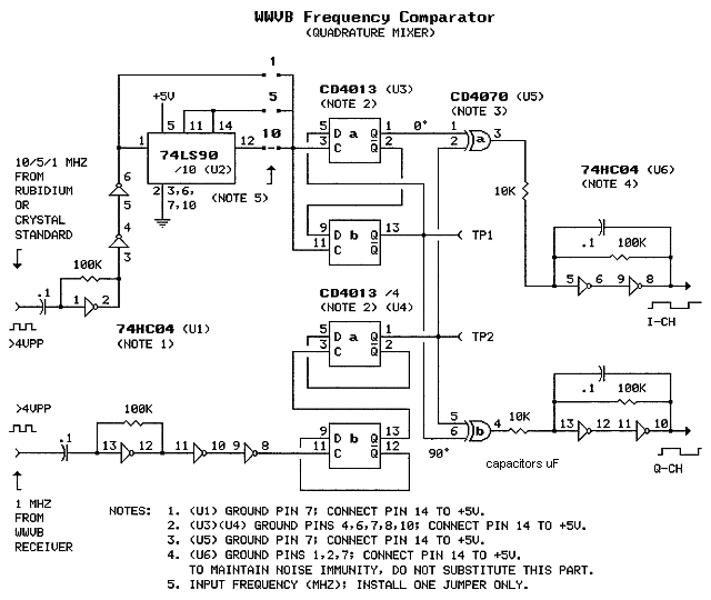
The circuit is basically a quadrature mixer: It subtracts the frequency of one input from the other and outputs the difference frequency. Digital dividers preceding the phase comparators comprising the mixer first scale the inputs from the WWVB receiver and Rb standard to a common frequency of 250 kHz. [The 10 MHz input from the Rb standard is divided by 10 and presented to a 90-degree phase shifting network which further divides by 4. The 250 kHz quadrature-phased outputs from the phase shifting network are presented to one input each of the phase comparators. The 1 MHz reference output from the WWVB receiver is divided by 4 and presented (not phase-shifted) to the other two phase comparator inputs.] The phase information is conveyed in the duty cycle of the pulses coming from the two phase comparators. The pulses are integrated and converted to digital logic level by LP-filter/Schmitt trigger circuits. (The explanation of the LP Filter/Schmitt trigger circuits is shown on a separate page.) The quadrature-phased outputs from the LP/STs are connected to the stepper motor driver which converts logic level inputs to bi-directional currents in the motor windings.
Schematic Diagram - WWVB/Rb Frequency Comparator
(Figure 1)
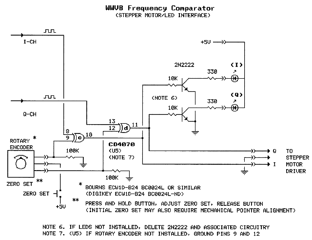
Schematic Diagram - WWVB/Rb Frequency Comparator
(Figure 2)
Includes Optional Zero Set and Indicator LEDs
Click here to see the LEDscope, an alternative to the I/Q indicator LEDs.
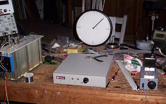
The Comparator Circuit Installed in a Case

The case, which once held a computer hard drive, came equiped with a 5V/12V power supply. The comparator circuit is on the gray protoboard. The indicator LEDs and zero set have not yet been installed.The box on the left contains the power supply. The fan and AC outlets on the rear panal are superfluous. The stepper motor driver is the small green board in the foreground. The bundle of yellow wires is an interface to a computer parallel port. (The computer interface is not shown in the above schematics. See computer-interfaced version.)
Stepper Motor and Driver Board

This motor and the driver board were salvaged from a receipt printer. The motor is a Shinano Kenshi STH-39C803, 0.9 degrees per step (400 steps per revolution), 6.8V, 16 ohm. The driver board has two Unitrode (now TI) UC3717A driver chips. The board circuitry appears to have been lifted directly from the UC3717A data sheet. The chip features programmable current limiting (via jumpers to programming pins), which allows the motor to be operated at much greater than its rated voltage for increased stepping torque without damage. For this application, the motor is operated at 12VDC with the driver jumpered for minimum current.
Stepper Motor Mated to Comparator

Note that a pointer (cable tie) has been glued to the motor shaft, and that the indicator LEDs, zero set button and zero set control have been installed in the comparator's front panal.
Trial Run - Comparator Tested with an Ovenized Crystal Standard.
The Electronic Research Co. EROS-750-PE-20 ovenized crystal standard,
the silver-colored thing on the right, is a clone of the HP 10544A.

In the first test of the system, the crystal standard was operated for about 2.5 hours (9000 seconds). In that time the pointer moved 90 degrees clockwise. (see 1) Since it takes 400 steps for a complete revolution, 90 degrees represents 100 steps. Each cycle of "slip" at 1 MHz (the frequency at which the comparison is made, see box below) generates one step pulse. So, to characterize the standard under test, one would count the pulses (with the stepper, equipped with a pointer), multiply by 1/1000000 (move the decimal point six places to the left) and divide by the elapsed seconds. The number of steps in this case was +100 and elapsed time was 9000 seconds. The calculation would be 100-6 / 9000 = 1.1/108. This is the error factor over the elapsed time.
I tweaked the crystal standard a little (it has a fine freq voltage control input which allows very fine adjustment with a 10-turn pot) and tried the test again. This time 100 steps required 10 hours (36000 seconds). 100-6 / 36000 resulted in an error factor of 2.8/109.
Testing the Rb Standard

The Scale

The Scale Up Close

The test ran 44 hours and accumulated 7 steps in the counterclockwise (negative) direction. (see 1) The frequency error factor calculates to -4.42/1011. Not bad! Long-term ageing rate specs for rubidium standards are usually in the range of ±5/1011 per year. To be within that spec after 8-10 years of operation, is pretty good indeed! I'd say I've got myself a rubidium frequency standard! (see 2)
Final Pointer Implementation
The round thing is an old clock with the stepper motor installed in place of the clock movement. This is a variation on the classic "synchroscope" display. Click here to check out the "LEDscope", an alternative to the stepper motor synchroscope.
The ERC ovenized standard mentioned above, with its 10-turn frequency adjustment pot, can be adjusted so as to keep the pointer virtually stationary for several hours at a time. However, it will not stay closer than a few parts in 109 over longer periods (for comparison with HP10544A see 3). Changes in ambient temperature and normal aging seem to be the cause of most of the variation.
An associated article describes how a long-term frequency comparison can be done using a computer in place of (or in addition to) the stepper motor.
Addendum 1
CW vs CCW
If you are unsure of how the direction of motor rotation correlates to the direction of frequency error, the correlation can be checked with a signal generator. I made a short movie showing this. The movie shows 1 MHz from the WWVB RX compared to 0.999960 MHz from a signal generator. The difference frequency is -40 Hz. Note that the stepper is turning counter-clockwise (at 1/10 revolution per second). In this case the correlation is direct: Negative frequency error produces counter-clockwise shaft rotation; positive frequency error produces clockwise shaft rotation. If the direction of rotation is not to your liking, it can be reversed by reversing one pair of motor winding leads.
back
Addendum 2
Rb Standard - Vertical vs Horizontal?
The rubidium standard was subsequently tested for a month using the computer interfaced version comparator. The standard was oriented horizontally during that test, as it would have been normally mounted in an equipment rack (vs vertically in the above test). After about a week of burn-in the frequency settled to less than 2 parts in 1012, an order of magnitude better performance. During a 10-day portion of the test the Rb standard generated no phase slips, making the actual error during that period incalculable, but for sure less than ±1.6 parts in 1012. [I am very impressed.]
Should the 90° rotation of the Rb standard - from vertical to horizontal - have made the difference? Evidently, the orientation of frequency standards with respect to Earth's gravitational field does make a small difference in output frequency. I found this paper: The Effects of Acceleration on Precision Frequency Sources. It reports on the results of a 2-g Tipover Test among other acceleration tests.
Addendum 3
ERC EROS-750-PE-20 vs HP 10544A
Later tests, using an old, presumably well-aged, HP 10544A, adjusted using the computer-interfaced version of the comparator, showed performance about an order of magnitude better than the ERC unit. To be fair, the ERC unit was new-in-the-box surplus - probably a factory reject - while the HP unit was pulled from working equipment. The 10544A was later modified with an external EFC voltage reference on pin 7 (required cutting an internal jumper) and retested. The modified 10544A demonstrated phenomenal medium-term [24 hour] stability - nearly equal to that of the rubidium standard [~5/1011]. here
top↑
Schematics produced with DCCAD.
