Receiver Modification Details.
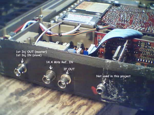
Three holes are drilled in the cases of the two radios and 3 BNC jacks installed, through which connections to the various points in the receiver are made with 50-ohm Teflon-dielectric mini-coax jumpers. The coax shielding is grounded at both ends.
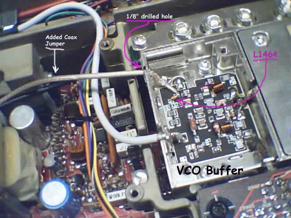
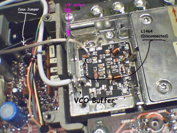
A small hole (1/8 inch) is drilled in the side of the VCO buffer in each radio to allow connection to the VCO buffers.
The connections to the VCO buffers are made at the junction of L1464 and R1466.
L1464 is disconnected on the buffer of the receiver designated as the #2 (slave) receiver.
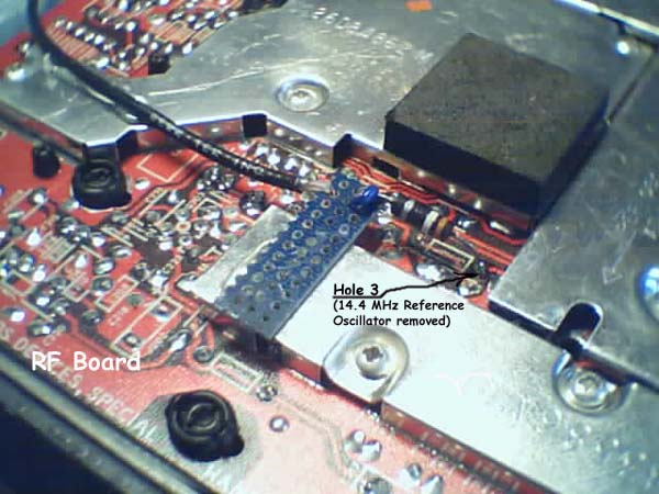
The 14.4 MHz reference oscillator is removed from the RF board on both receivers (master and slave) and connections from the designated BNC jacks (14.4 MHz Ref IN) are made to hole 3 through the components shown.
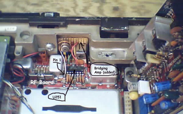
An IF bridging amplifier is glued to the case next to U251 (FM detector) of each radio and connections are made to U251. The output of each bridging amplifer is connected to its corresponding IF OUT jack with mini-coax.
Also (not shown), L607, L608 and Q611 are removed from the RF board of the slave radio. This totally disables the synthesizer in the slave radio. This step may not be strictly necessary, but we did it anyway.
