Junk Box Retro
Electronic Attic Fan Thermostat
Max Carter
OK, I could easily have coughed up $25 or so for a line-voltage SPDT mechanical thermostat, but decided instead to build an all electronic one with stuff from my junk pile and a few never-used old-stock components. Some scrounging, drilling and proto board fabricating produced this retro (~1970s-80s) electronic thermostat. The incremental dollar cost came in at a big fat zero, but more importantly, the project was fun and educational. You may find it interesting even if you have no need for an attic fan thermostat.
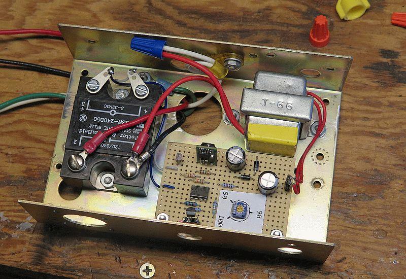
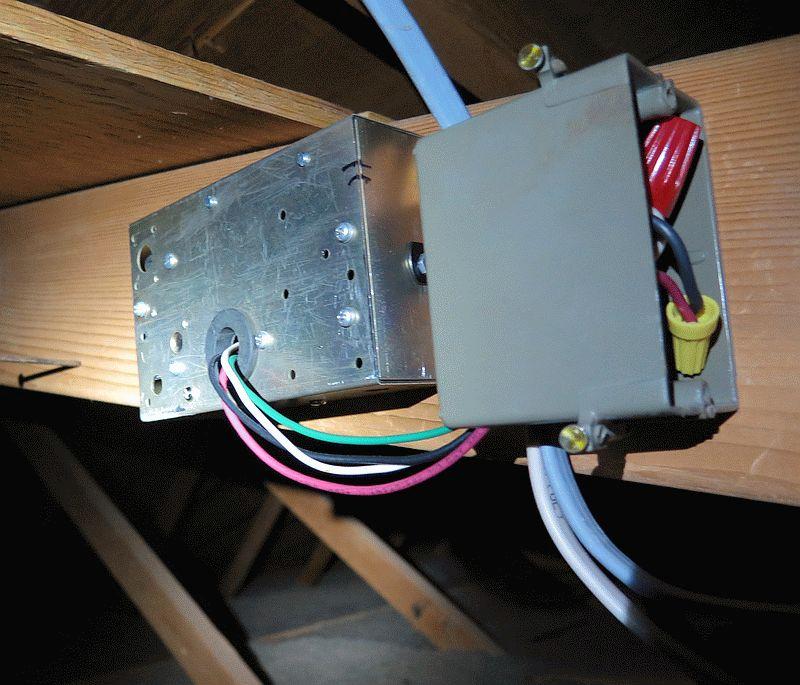
Since the unit would be a set-and-forget thing, hidden away in the attic and likely never seen again, I wasn't too interested in making the project look pretty. It fulfilled that non-goal, as you can see.
Inside

Mounted in the Attic

Thermostat Circuit


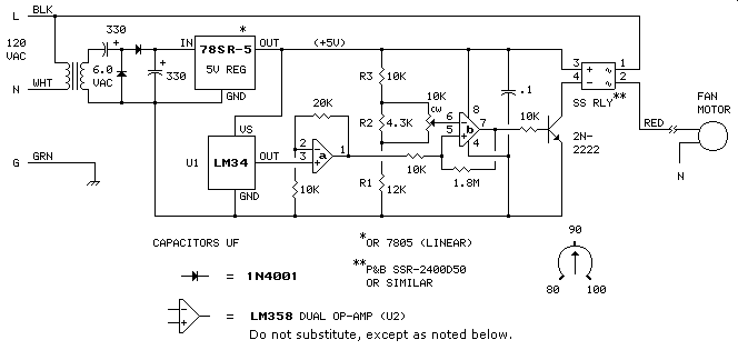
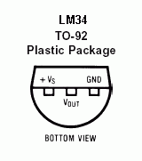
The circuit is based on the LM34 Fahrenheit temperature sensor from TI. The sensor outputs (on the Vout pin) 10 millivolts per degree F above 0°F. So, for example, 80°F produces 800 mV or 0.8 volts. The first opamp (U2a) amplifies the sensor voltage by a factor of three ⇒ 80 degrees produces 2.4 volts at the output (pin 1), 90 degrees produces 2.7 volts, 100 degrees produces 3.0 volts and so on. This voltage is compared with the voltage from the wiper of the 10k potentiometer (which can be set anywhere from 2.4 volts to 3 volts) by U2b. If the output of U2a is greater than the voltage from the potentiometer, the output of U2b goes high, turning on the 2N2222, energizing the solid-state relay and turning on the fan. Same thing in reverse on the trip down: when the output voltage from U2a is lower than the wiper voltage, the output of U2b goes low, shutting off the fan.
Some Fine Print
- Any transformer with a secondary output rating of 3 to 12 volts AC can be used in the above circuit. For transformer secondary voltages between 6 and 24, the power supply can be simplifed as shown below. The circuit's current draw is minuscule.

- For operation in a 240 VAC system, substitute a transformer with a 240-volt primary rating for the 120-volt one shown. The P&B SSR-240D50 SS relay is rated for 120/240 volts.
- Any flavor 7805 linear voltage regulator could substitute for the 78SR-5 switching regulator shown. I just happened to have the 78SR-5 on hand.
- Any small-signal NPN transistor could substitute for the 2N2222 shown.
- The 1.8M resistor sets the thermostat's hysteresis gap. The value shown provides a gap of about 1°F. Decrease this value to increase the gap. For example, 910K produces a 2° gap. 620K produces a 3° gap, etc.
- The P&B SSR-240D50 solid-state relay shown, like everything in this project, came from my junk pile. It's 50-amp rating is gross overkill for the 1/70 HP fan motor in the attic. Virtually any 3-32 VDC SSR with a current and voltage rating equal to or greater than what is required for the motor could be used in the circuit. Current-driven (10 mA) SSRs require a 330-ohm current limiting resistor in series with the input.
- The voltage divider components R1, R2 and R3 shown produce the 80-100° scale for the set-point potentiometer. Other scales can be accommodated, including Celsius. Some examples are shown in the table below. The value of R2 assumes a 10k set-point potentiometer. One percent resistor values are shown, but nearest 5-percent values would likely work well enough.
Range R1 R2 R3 80-100°F 12.1k 4.32k 10.0k 50-100°F 7.50k 30.1k 10.0k 80-120°F 12.1k 15.0k 6.98k 50-120°F 7.50k ∞* 6.98k 25-40°C 11.5k 6.81k 9.31k 10-40°C 7.50k 42.2k 9.31k 25-50°C 11.5k 21.0k 6.65k 10-50°C 7.50k ∞* 6.65k *Open circuit; R2 not installed.
- The industry standard LM358 opamp (now made by TI) has some unique features useful in this circuit: operable with single power supply, input voltage range includes ground, output voltage range includes ground. Substitute other vendors' opamp only with a type recommended by the vendor's cross-reference chart. The LM324, which is a quad version of the LM358, would substitute with appropriate changes to the pin connections.
- Even though I'm calling the circuit "retro", every component shown is widely available today.
Schematics produced with DCCAD.