My daughter worries about me. I live 75 miles from her, out in the country, with no close friends or neighbors. So, partly to ease her concerns, but mostly because I like interesting projects, I decided to brew up a "Has Dad dropped dead?" application based on the computer that hosts this website, an old Windows XP PC sitting on a bench here in my lab/shop/studio. The machine, connected to a protected power source (UPS), runs 24/7. The server on the machine is Apache2, with ActivePerl installed to help run some of the web applications. Perl can do lots of neat stuff and it's what makes this project feasible: It's already there and it's on all the time.
The keep-tabs-on-dad idea was to pick an often-used electrical device or appliance in the house (or multiple devices and/or appliances) and monitor it for activity (on/off operations) and report that activity, or more importantly lack of activity, to my daughter's smart phone via email. The 'device' chosen was the light in my bathroom.
Here's the Concept
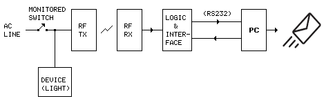
Here's the series of events:
- The light is switched on, energizing the transmitter (RF-TX). The receiver (RF-RX) indicates a valid signal is present.
- The light is switched off, the transmitter goes off. The receiver indicates no signal.
- Logic detects the fact that an on/off cycle has occurred and sets an output flag.
- The interface reports to the computer (when polled): "Activity noted" (sends ASCII chr #49). How often the computer polls is determined by a Perl script in the computer, triggered by Windows Scheduled Tasks. Once every 12 hours might be a reasonable interval, but the polling interval could be as short as 1 minute.
- If no activity is noted within the polling interval the computer sends an email, via gmail, to the person or persons who may be concerned, "No activity reported last 12 hours!" for example.
- If a longer interval goes by (a week seems reasonable) with normal daily activity noted, the computer sends an email (or emails) informing the concerned individual(s) of that fact - ie, "Normal activity noted, last 7 days." (This provides a weekly functional test of the system.)
- If for some reason the computer is unable to transmit the email (fails to connect with gmail), the program aborts, waits for the next polling interval and tries again.
The envisioned system does not provide for instant emergency medical response (or instant anything). The goal is limited to reassuring the concerned individual that the monitored individual is up and about, not lying dead on the floor or otherwise incapacitated. And, if the monitored individual IS lying dead on the floor, the monitored individual will not be in an advanced state of decomposition by the time of eventual discovery. The as-built system has lived up to expectations.
The Hardware
The first issue was linking the monitored device, that is, getting the data from the monitored device, remote from the computer, to the computer. In this age of wireless everything I certainly didn't want to run wires. A pair of RF Digital's RFD21733 wireless transceivers, used in countless doorbells, garage door openers and keyless entry systems, seemed to be the way to go. The second issue was the logic and interface. Since I am somewhat familiar with the PICAXE 08M microcontroller, having incorporated the chip previously in a couple of projects interfacing the computer to external sensors (see Web server/PICAXE Interface and PICAXE Outside Temperature/Internet Project), and having a half-dozen on hand, decided to use the chip (it ended up being 2 chips) in the project to interface the computer.
RFD21733 and 08M
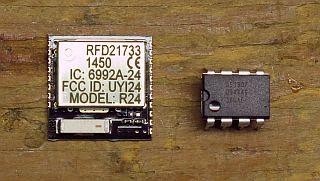
The RFD21733 is 15mm x 15mm (.6" x .6").
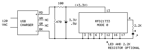
The Monitoring Circuit
(The transmit end of the monitor link.)
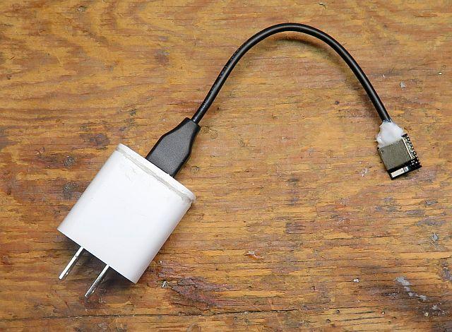
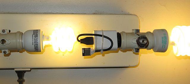
It could hardly be simpler. For this application, the RFD21733 is configured for "Mode 0" (by grounding all 'mode' pins; there are 8 modes (see RFD21733 data sheet). In this mode, when 3.3-volt power is applied, the transceiver immediately begins transmitting, in bursts every 2 seconds, its unique 32-bit ESN (Electronic Serial Number), encoded in such a way that the receive end, using an error-correcting algorithm, can decode in the presence of noise and interfering signals. The RFD21733 continues to transmit as long as power is applied. Power comes from a 5-volt USB charger, regulated to 3.3 volts through a series resistor and 3.3-volt zener diode. The RFD21733 is connected to the end of a USB cable (along with the voltage regulating components soldered to the underside), the cable plugged into the charger and the charger plugged into a spare light socket on the fixture. When the light is on, the socket is hot and the RFD21733 is transmitting. When the light is switched off, the socket goes dead and the RFD21733 stops transmitting. That's it!
Figure 1
Monitor Transmitter Schematic
RFD21733 Pinout
Top View
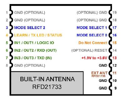
Note: Pins 1, 2, 8, 9, 10, 12, 18, 19 are connected internally. Any of those can be used wherever a ground is required.
Connections Underside of RFD21733 (TX)
Regulator Components Installed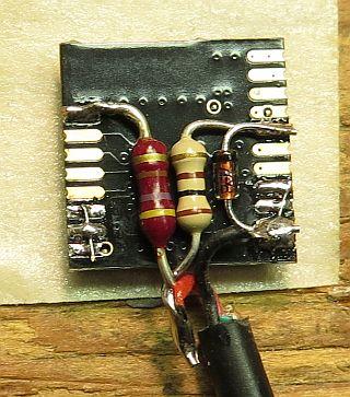 |
LED and Resistor Installed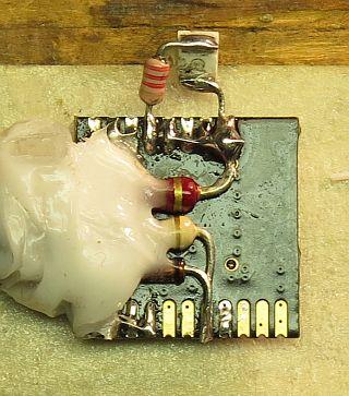 |
The white stuff is RTV silicone.
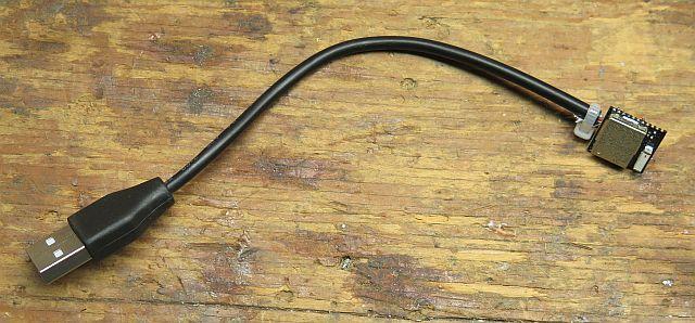
Connected to USB Cable
Mated to USB Charger
Plugged into Light Socket
The Monitor Receiver/Computer Interface
(The receive end of the remote monitor link.)
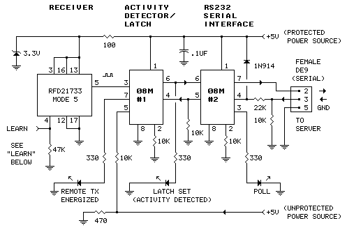
Another RFD21733 is used to receive the signal from the monitor transmitter, in this case configured for "Mode 5" (see RFD21733 data sheet). In this configuration, the transceiver outputs a 500mS positive-going pulse every 2 seconds as long as a valid signal is being received from the far end of the link. When the signal stops, the output stays low.
A couple of PICAXE 08M chips are used to detect receiver activity and convey it to the computer. 08M number one (#1) acts as a integrating timer and latch. The timer detects the presence of pulses from the receiver (RFD21733). "Activity" is reported only when a complete on/off cycle of the monitored appliance (the light) occurs. Thus, if the light is accidentally left on, the timer's output latch will not be set until such time as it is turned off. A light left on or off will eventually be reported as "No Activity". The second 08M (#2), when polled by the computer, reports the state of the timer's output latch and issues a pulse to reset the latch for the next occurrence. The idea here is not to count the times the light is switched on and off, but to report when it has not occurred within the sample interval.
And what if the power fails? Under certain conditions - the bathroom light left on, for example - a power failure and subsequent restoral might be misinterpreted as "normal activity". That it is not misinterpreted is based on the fact that power failures are not local. If the power fails in the bathroom, it also fails in the computer room. If the interface notices that power has failed, it ignores input from the remote and locks up in whatever state it happens to be in at the time. When power is restored, the interface resumes normal operation in its before-failure state (unless it happens to have been reset by the computer - the interface retains its ability to talk to the computer through a power failure).
Figure 2
Computer Interface Schematic
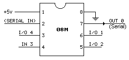
PICAXE 08M Pinout
Connections Underside of RFD21733 (RX)
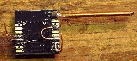
The thick wire on pins 9 and 10 serves as a counterpoise to the antenna. It improves antenna efficiency.
Completed Interface Board
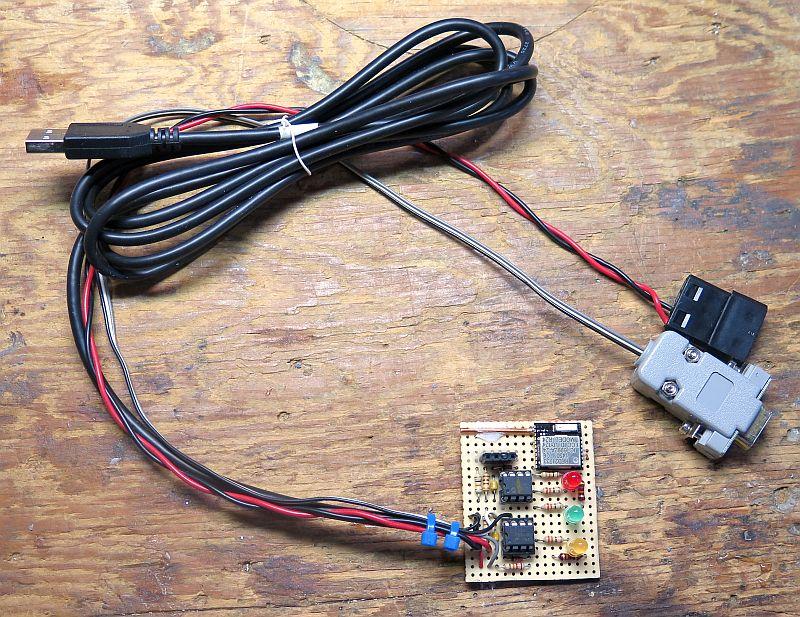
The gray connector is a female DE9; it plugs into the computer's serial port. The red/black wire provides protected 5 volts DC; it plugs into one of the computer's power supply connectors. The USB connector plugs into an unprotected 5-volt power source. This could be a USB charger (as in Figure 1), but in this case it's connected to a USB port on another computer, not power-protected, next to the server. (The USB ports on computers are hot whenever they're plugged into a hot outlet and go dead when the outlet goes dead, regardless of whether or not the computer is running.)
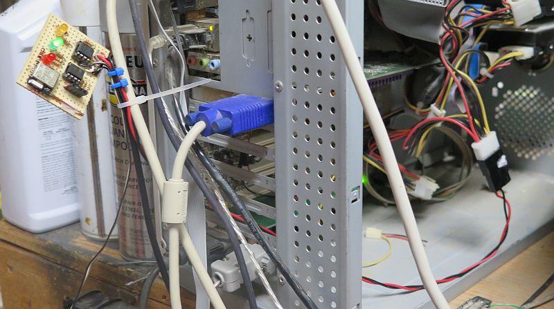
Interface Board Attached to Computer
Connection to Serial Port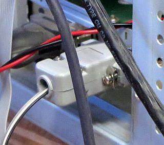 |
Power Connection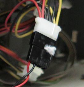 |

See also: Scheduling the Polling Interval starting below 'Firmware/Software'. ↓
Firmware/Software
Three programs are shown below, two for the 08M chips (in PICAXE Basic), and one for the Perl script that runs on the computer.
08M #1
Copy the following code to the PICAXE Programming Editor and program the chip (works also on 08M2 chip):
'initializes on power up,

	pause 100	'100mS

	low 0		'sets remote signal LED (pin 7) to "not present"

	low 1		'sets activity (pin 6) to "no activity"

	b0 = 50 	'sets accumulator count to 50

	b1 = 0	'sets accumulator output to 0

	b2 = 0	'sets cycle delay memory to 0


power_check:

	if pin3 = 1 then  'IF input 3 (pin 4) high, (this comes from PIC#2)

	low 1    ' resets output latch,  (pin 6) low

	endif

	if pin2 = 1 then  'if input 2 (pin 5) high (high here indicates power OK)

	goto execute

	else

	pause 100

	goto power_check

	endif


execute:

	pause 100 'milliseconds, establishes sample rate at about 10 per second

	ReadADC10 4, W5	'reads voltage on input 4 (pin 3) from the RFD21733 receiver

	if W5 < 340 then	'less than about 1.65 volts, (half of 3.3 volts)

	b0 = b0 - 1		'discharges accumulator (b0), approx 20 second discharge (4 seconds on powerup)

	else b0 = b0 + 10	'charges accumulator; charge rate 10 times faster than discharge rate

	endif

	if b0 > 240 then	'limits max value b0 to 240

	b0 = 240

	endif

	if b0 < 10 then	'limits min value b0 to 10

	b0 = 10

	endif

	if b0 > 60 then	'accumulator output toggles high

	b1 = 1

	high 0	'remote signal present, (pin 7)

	elseif b0 < 40 then	'accumulator output toggles low

	b1 = 0

	low 0		'remote signal not present (pin 7)

	endif

	if b2 > b1  then  'this comparison looks for a 1 to 0 transition  ("activity")

	high 1	'sets output latch ("activity detected") (pin 6)

	endif

	b2 = b1	'shifts contents of b1 to b2, retains the state of b1 for comparison in the next cycle

	goto power_check   'restarts check/sample/accumulate cycle
08M #2
Copy the following code to the PICAXE Programming Editor and program the chip (works also on 08M2 chip):
main:

	serin 3, N2400, ("c="), b0 'waits here for input from computer, gets character after qualifier ("c=")

	if b0 = "d" then 'looks for "d"

	high 4	'(pin 3) lights "polling" LED

	if pin1 = 1 then  'gets input from latch, on pin 6

	serout 0, N2400, ("1", 13)  'sends ASCII chr "1" to computer; 13 is CR,

	high 2  'sets output 2 high, resets latch in PIC #1

	pause 200  '200ms

	low 2  'sets output 2 low

	else serout 0, N2400, ("0", 13)  'sends ASCII "0" to computer; 13 is CR

	endif

	pause 300

	low 4		'extinguishes 'poll' LED

	endif

	goto main
Perl Script
Requires late-model ActivePerl installation
[Community Edition (free), here]
|
And modules:
|
Copy the following code to your favorite text editor; edit the email message header (From:, To:, Cc:, Subject:) and body ($senddata) as appropriate; add your gmail account information (address and password*), recipient addresses, and the path (c:/folder/etc) to the /time_ref.txt file (use forward slashes). Save the file (with .pl extension, eg, "monitor_dad.pl") to a location on the computer:
use strict;

use warnings;


my $time = time;  #gets current time (computer time in seconds)

my $stoptime = $time + 2;	#adds 2 seconds

my @recipients;  #list of email recipients

my $subject;	#subject line of the email

my $senddata;	#this will be the email message body

my $status;		#status (1/0) of PICAXE interface latch


use Win32::SerialPort;


my $Sport = Win32::SerialPort->new('COM4');  #this creates an object, named $Sport,
						#that provides a connection to COM4
						#make this any available COM port you like

$Sport->baudrate(2400);		#configures serial port
$Sport->parity('none');
$Sport->databits(8);
$Sport->stopbits(1);
$Sport->handshake('none');
$Sport->write_settings;


sub get_status($)  {		#subroutine gets status of monitor interface latch (PICAXE #1)

	$Sport->write("c=d");	#sends command to interface, "c=" is qualifier, "d" is command

	$_ = '';			#clears (sets to 'nothing')

	do {		#this will stop the program if it does not hear back from the interface within 2 seconds

	$time = time;	#gets computer time

	if ($time >= $stoptime)  {		#if current time greater than or equal to stoptime,

	die "no response from interface";

	}

	$_ .= $Sport->read(1);	#reads serial port chr, ".=" means concatinate

	}

	while (!/\r/);    	#until carriage return (\r) received

	return $_;		#ends do-while loop, returns value

	}


$_ = get_status ("");		#calls the get_status subroutine above

$_ =~ (s/\r//);			#gets rid of the CR - substitutes '\r' with ''(nothing)

$status = $_;

undef $Sport;		#destroys serial port object

if ($status != 1)   {   #if not "1", ie, if latch not set

no_activity();   #calls no_activity sub

}

else   {

normal_activity();   #calls normal_activity sub

}


sub no_activity    {	#sends "no activity" email


	@recipients = ("intendedrecipient\@whatever.com","somebodyelse\@wherever.com");  #address of
				#'intended recipient'and 'somebody else', 'somebody else' optional,
				#any number can be added, separate addresses with commas, must be valad addresses
				#note added backslash "\" before "@" must be present (very important)

	$subject = "Dad: NO ACTIVITY :(";		#or whatever you want here

	$senddata = "NO ACTIVITY RECORDED LAST 12 HOURS! Check on dad!  :(";	#email message body
										#your message here

	send_email();	#calls send_email sub


	}


sub rpt_interval_start   {		#get reporting interval start time  (from time_ref.txt file)

	open (my $fh, "<", "path/time_ref.txt");  #$fh is "file handle", opens for read

	while (<$fh>)  {		#reads interval start time, "<>" means readline until \r

	return $_;

	}

	close $fh;

	}


sub normal_activity    {

	$_ = rpt_interval_start();		#gets interval start time from rpt_interval_start sub above

	if  ($time > ($_ + 600000))  {   #if one week has passed (1 week = 604800 seconds) sends "normal activity" email


	@recipients = ("intendedrecipient\@whatever.com","somebodyelse\@wherever.com");
			#address of 'intended recipient' and 'somebody else' (as many as you like)
			#(may be differerent from @recipients in no_activity sub above)
			#somebody elses optional, separate addresses with commas,
			#must be valid addresses
			#note backslashes "\" before "@" (very important)


	$subject = "Dad: Normal activity";	#or whatever

	$senddata = "Normal activity noted, last 7 days.  :)";	#email message body

	send_email();		#calls email sub, "()" needed to keep 'strict' above happy

	}

	}


sub send_email  {

	use Net::SMTP;

	my $smtp = Net::SMTP->new('smtp.gmail.com', SSL => 1, Debug => 1);  #Googlemail requires SSL

	$smtp->auth('youremailaddress@gmail.com', 'app password');	#Gmail requires authorization

							#you must have a gmail account,
							#The account holder must create a 16-digit 'app password'
							#see: https://support.google.com/accounts/answer/185833?hl=en

	$smtp->mail('youremailaddress@gmail.com');

	$smtp->recipient(@recipients);

	$smtp->data();
	$smtp->datasend('From: You '."\n");
	$smtp->datasend('To: Recipient Name'."\n");
	$smtp->datasend('Cc: Somebody Else'."\n");
	$smtp->datasend("Subject: $subject\n");
	$smtp->datasend("\n");  #end of header
	$smtp->datasend("$senddata\n");
	$smtp->datasend("");
	$smtp->dataend();
	$smtp->quit;

	write_current_time();		#calls write_current_time sub

	}


sub write_current_time  	{	#writes current time (interval start time) to time_ref.txt file,
					#starts new reporting interval

	open (my $fh, '>', 'path/time_ref.txt');  #opens file for write (overwrite)

	print $fh "$time\r";	#writes current time to file

	close $fh;

	}
Scheduling the Polling Interval
This is done with "Scheduled Tasks" on older PCs (XP, etc) or "Task Scheduler" on later models, usually under "accessories" somewhere in the start menu. "Task" is set to the location of the Perl script on the computer (path\filename.pl); "start time" is set to midnight on some day convenient for the recipient (say, Friday); "repeat task" is set to the desired polling interval (12 hours, etc). Keep in mind that the "polling interval" is the time between polls of the interface. The "reporting interval" is the time between transmissions of the normal activity email.* If any polling interval passes with no activity, the program does not wait for the reporting inverval. The no activity email is immediately sent.
*The reporting interval can be changed by editing the line "if ($time > ($_ + 600000)) {" (1 week = 604800 seconds).
Parts:
|
RFD21733 - |
The RF module used in this project has been discontinued by the manufacturer but old stocks are still available from suppliers. Google search "RFD21733" and/or variants "RFD21735" (external ant.) and "RFD21813" (DIP) and "RFD21743" (radio in ant.). eBay is always a good place to look: eBay |
| PICAXE 08M2 - | Sparkfun PICAXE.com |
Schematics produced with DCCAD.
Related Articles
Communicate with the PICAXE
PC Communicates with the PICAXE and the INTERNET
PICAXE Outside Temperature/INTERNET Project
Anemometer/Computer Interface

My cat Squish has been very helpful in getting details of the project published to the Web.
Here he is checkin' the prints..