PICAXE Microcontroller
Communicate with the PICAXE
See also related article: Web Server/PICAXE Interface
The PICAXE is programmed with the PICAXE Programming Editor via a serial interface cable. But how do you communicate with the chip, say to control external devices or extract data, once it's programmed?
The PICAXE chips allow serial communications on many (but not all) of their I/O pins. You can always "talk" to your chip using the developer's terminal program included in the PICAXE Programming Editor, but there may be situations where you may not have or want the programming editor installed on the machine you (or your customer) will be using as your working control center. Also, the terminal feature in the Editor communicates via the same Com port as the programmer. This may introduce a hassle factor in that it forces you to use the SERIAL IN/OUT programming pins on the chip for communication, or to move the serial cable each time a change to the program is made. In these situations you might want to use a separate terminal program to communicate with the PICAXE. This page shows how to use the ubiquitous Windows HyperTerminal for that purpose. This demonstration uses the 08M chip.
First Establish a Second Serial Connection
Since the designated SERIAL IN pin (pin 2) on the 08M can be used only for programming, it's necessary to establish a second, separate channel or "port" into the chip for communicating. For connection to a PC, the components connected to the serial input pin (10k and 22k resistor) must be duplicated on the pin you select for the second port. In the example below, the selected pin is pin 4 (In 3). For this particular pin, in addition to the resistors, a 1N914 diode must be connected from pin 4 to the +5v power rail, cathode end to pin 1, as shown.

The cable which connects port 2 to the computer is a duplicate of the cable used for programming the PICAXE chip. In fact, the same cable can be used for both functions, but it must be moved to the appropriate port when switching between the functions. If you will be making lots of programming changes, it probably will be worthwhile to make up TWO cables - it's one of the reasons for using a separate terminal program in the first place.
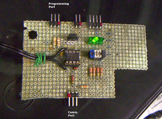
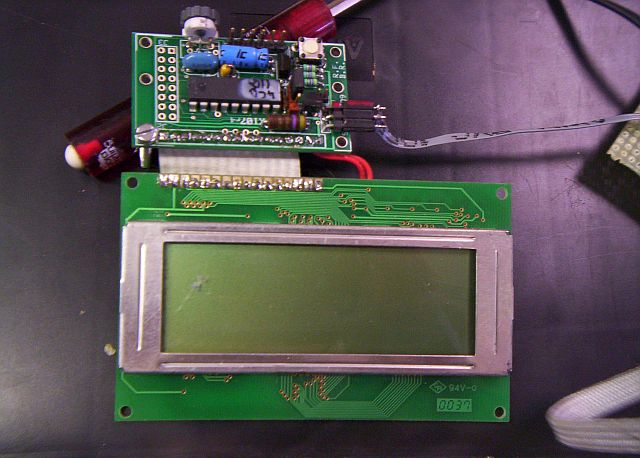
My 08M Board
Note separate programming and comm ports.
Set Up the Terminal Program
HyperTerminal is a terminal emulation program supplied with the Windows operating system up through WinXP. It will be found under Accessories if it's on your machine.
Run HyperTerminal.
The program may ask if you want to make HyperTerminal your default telnet program - check no, and do not ask me again.
The program may ask if you want to install a modem - check no.
The program will eventually bring up a New Connection window, asking you for a name and icon for the new connection. Type in a name and select an icon (if any are shown). Click OK.
The program will then bring up a window asking how you would like to connect. Select Direct to Com1 (or Com2 - Com8). Note: If the same cable will be used both for programming and communication, the specified Com port must be the same as the port specified in the PICAXE Programmng Editor. If separate cables will be used, specify a different port. Do not enter any telephone numbers. (You may have to enter your area code.) Click OK.
The program will then ask for the port settings. Select 2400 bits per second, 8 data bits, no parity (None), 1 stop bit, and no flow control (None). Click OK. HyperTerminal will then connect to the selected port. Tapping the keys on the keyboard should not produce any characters on the computer screen at this time. If it does, click file and properties (or click the Properties button); click the Settings tab; click ASCII setup button; uncheck the Echo typed characters locally box.
Click file and save to save the connection settings. (Windows may suggest the appropriate place to save the settings. Go with the suggestion.) Find the .ht settings file (that you just saved), create a shortcut and drag it to the desktop.
[Note: It is not necessary to go through the steps to set up HyperTerminal each time it is opened. Simply click on the connection setup name (the name you gave it during the initial setup) and icon on the desktop to retrieve the settings and start HyperTerminal.]
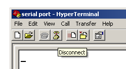
HyperTerminal must be disconnected from the computer's Com port if the same port and cable will be used for programming the PICAXE. Do not disconnect the serial cable from the computer's Com port. Click on the little telephone to disconnect HyperTerminal. Minimize HyperTerminal.
Program the PICAXE
Bring up the PICAXE Programming Editor. Copy the following program to the editor. Verify that the programming cable is connected to the correct port on the computer and the PICAXE board. Program the chip.
main:

	SerIn 3, N2400, b0  'gets character from computer

	SerOut 0, N2400, (b0)   'echos character back to computer

      goto main
Verify it Works
Reconnect the serial cable on the PICAXE board if necessary (move the cable from port 1 to port 2). Bring up HyperTerminal and re-connect (click the little telephone). Tap some keys on the keyboard. Each key tap should produce the corresponding character on the computer screen. It's that simple. You are now communicating with the PICAXE!
What if it Doesn't Work?
- Verify Hyperterminal is connected to the correct Com port on the computer. If you are using the same cable to connect with HyperTerminal that you use for programming, the specified Com port must be the same as the one used for programming.
- Verify HyperTerminal is sending and receiving data. Remove the programming/comm cable from the PICAXE board and place a jumper from pin 1 to pin 2 of the connector at the end of the cable (the PICAXE end of the cable). A paper clip works pretty well for this. This loops the transmit pin back to the receive pin. With the jumper installed, tapping a key on the keyboard should produce the corresponding character on the computer screen. If it does not, HyperTerminal is not connected to the correct port on the computer. If it does, there is some problem on the PICAXE board. Be sure the cable is attached to Port 2 on the PICAXE board.
Another Communications Demonstration
This section demonstrates how the PICAXE can be used to communicate with other devices in a system. In this case the other device is the K107 LCD display controller, which many PICAXE experimenters may have acquired. (It could just as easily be another PICAXE chip. See some examples here.)
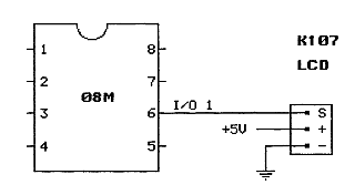
The K107 Display Controller
The K107 is the small board above the (4x20) LCD display.
Connection to the 08M
As you can see, Out 1 (pin 6) of the 08M connects to the K107 (pin S).
Also shown are the connections on the K107 to +5 volts and ground.
The Code
    High 1
    wait 5				'initializes LCD


   SerOut 1, T2400, ("?G420")	'configures LCD display as 4 X 20
				'configure for YOUR display


 main:


	SerIn 3, N2400, b0  'gets character from computer

	SerOut 0, N2400, (b0)   'echos character back to computer

   	SerOut 1, T2400, (b0)   'sends character to LCD

      goto main
As you can see, the 08M talks to the K107 in the same format that it talks to HyperTerminal (2400 bps), except that the format is inverted: "True" (the T in T2400) instead of "Normal" (the N in N2400).
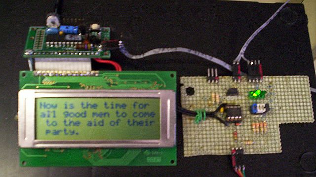
Type the characters on the PC in HyperTerminal
The "?f" clears the LCD screen and returns the cursor to the home position.
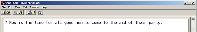
See the characters appear on the LCD
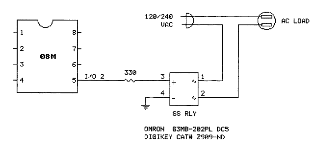
This Demonstrates How to Control Something
With this hookup we can turn a device like a light or motor on or off.
The "SS RLY" in the diagram is a solid state relay. In addition to controlling the external load,
it provides ISOLATION from the power line.
If you build this thing, do not connect anything on the PICAXE side of the relay to the power line!
The Code
	SerOut 0, N2400, ("Hit ENTER twice") 	'causes "enter command" prompt
						'to be sent to computer


 main:


	SerIn 3, N2400, b0  'gets first character from computer

	SerOut 0, N2400, (b0)   'echos character back to computer

	SerIn 3, N2400, b1  'gets second character from computer

	SerOut 0, N2400, (b1)   'echos character back to computer


	if b0 = "o" and b1 = "n" then  'looks for "on"

	high 2		'turns on the output (starts motor, turns on light, etc.)

	SerOut 0, N2400, ("  Verified: ON")'sends verification back to computer


	else if b0 = "o" and b1 = "f" then  'looks for "of" (off)

	low 2       'turns off the output (motor, etc.)

	SerOut 0, N2400, ("  Verified: OFF") 'sends verification back to computer


	else

	SerOut 0, N2400, ("  Bad command")  'sends if "on" or "of" (off) not received

	endif

	SerOut 0, N2400, (13,10,10,"Enter command:")  'sends new command prompt;

	'the "13,10,10" are the ASCII characters for Carriage Return and two Line Feeds

      goto main
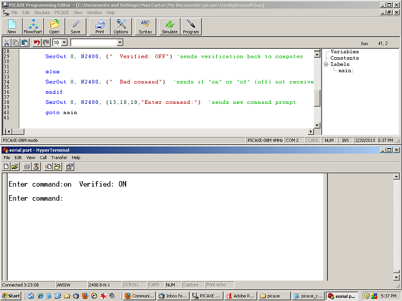
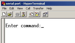
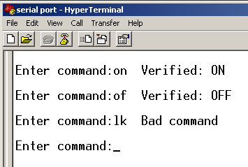
Here's what it looks like on the computer screen.
The PICAXE transmits a prompt to the computer, asking for a command.
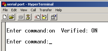
The command "on" is typed. The PICAXE turns on the output (sets it high), verifies that it has executed the command
and sends another prompt:
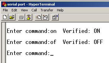
The command "of" is typed. (Yeah, yeah, I know. "Off" isn't spelled "of".) The PICAXE turns off the output (sets it low),
verifies that it has executed the command and sends another prompt.
A bad command ("lk") is typed. The PICAXE sends "Bad command" and sends another prompt.
This Demonstrates How to Get Some Data
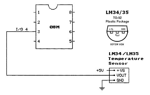
We can read a temperature sensor, for example.
The sensor is the LM34 "Precision Fahrenheit Temperature Sensor". If you'd rather do it in Centigrade/Celsius, substitute the LM35. The sensor is connected to the PICAXE like so:
The Code
The temperature code (get_temp) is shown here added as a subrouting at the end of the control code shown above, with a call to the subroutine after the "on" and "off" tests. Use the same code for reading the Centigrade (LM35) sensor. Since the ADC in the 08M can only read positive voltages, the code only works for temperatures above 0°.
	SerOut 0, N2400, ("Hit ENTER twice") 	'causes "enter command" prompt
						'to be sent to computer


 main:


	SerIn 3, N2400, b0  'gets first character from computer

	SerOut 0, N2400, (b0)   'echos character back to computer

	SerIn 3, N2400, b1  'gets second character from computer

	SerOut 0, N2400, (b1)   'echos character back to computer


	if b0 = "o" and b1 = "n" then  'looks for "on"

	high 2		'turns on the output (start motor, turn on light, etc.)

	SerOut 0, N2400, ("  Verified: ON")'sends verification back to computer


	else if b0 = "o" and b1 = "f" then  'looks for "of" (off)

	low 2  'turns off the output (motor, etc.)

	SerOut 0, N2400, ("  Verified: OFF") 'sends verification back to computer


	else if b0 = "t" and b1 = "e" then 'looks for "te" (temperature)

	gosub get_temp	'calls up "get_temp" subroutine below


	else

	SerOut 0, N2400, ("  Bad command")  	'sends if "on" or "of" (off) or
						'"te" (temperature) not received

	endif

	SerOut 0, N2400, (13,10,10,"Enter command:")  'sends new command prompt

      goto main


 get_temp:


	ReadADC10 4, W2	'reads the voltage on In 4; returns a value between 0 and 1023

	'The next three commands scale the ADC voltage reading to millivolts.
	'The scale factor (5.08) depends on the power supply voltage, which the ADC
	'uses as a reference in the 08M chip.  The scale factor is calculated by
	'multiplying the power supply voltage, as measured with a digital multimeter,
	'by 1000 and dividing by 1024.  The measured voltage in this case is 5.2 volts.
	'Thus, 5.2 x 1000/1024 = 5.08.  If you don't have a digital multimeter, use
	'the value 5.0 for the calculation. The scale factor in that case would be 4.88

	W3 = W2 * 5
	W3 = W2 * 0 / 10 + W3
	W3 = W2 * 8 / 100 + W3

	'The next two commands convert the millivolt reading to degrees. The LM34/35
	'generates 10 mV per degree, so degrees = millivolts/10.

	b6 = W3 / 10  'division by 10 generates whole degrees (the 08M doesn't do decimals)
	b7 = W3 % 10  'modulo division by 10 generates tenths of degree


	if b7 > 5 then 	'if tenths greater than 0.5,

   	b6 = b6 + 1	'moves to next higher whole degree


   	endif

	SerOut 0, N2400, ("  Temperature: ", #b6, " F") 'sends temperature data to computer
							'for LM35, substitute " C"
	return
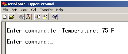
It looks like this on the computer screen
The command "te" is typed. The PICAXE reads the sensor and sends back the data.
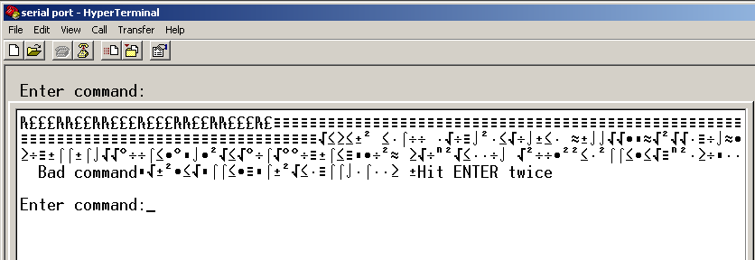
Gobbledegook
If you use HyperTerminal during a programming session and have arranged your PICAXE setup with two serial cables as I have, one for programming and one for communicating, you'll have to put up with some junk on the computer screen during the PICAXE chip programming process. If it's a problem, either disconnect HyperTerminal before each programming upload (with the little telephone) or use another pin, such as I/O 4 (pin 3), for communicating towards the computer. Press ENTER twice to get the prompt.
Gobbledegook