|
|
Listed below are the modifications, this time in order of increasing difficulty, sort of.
Easy:
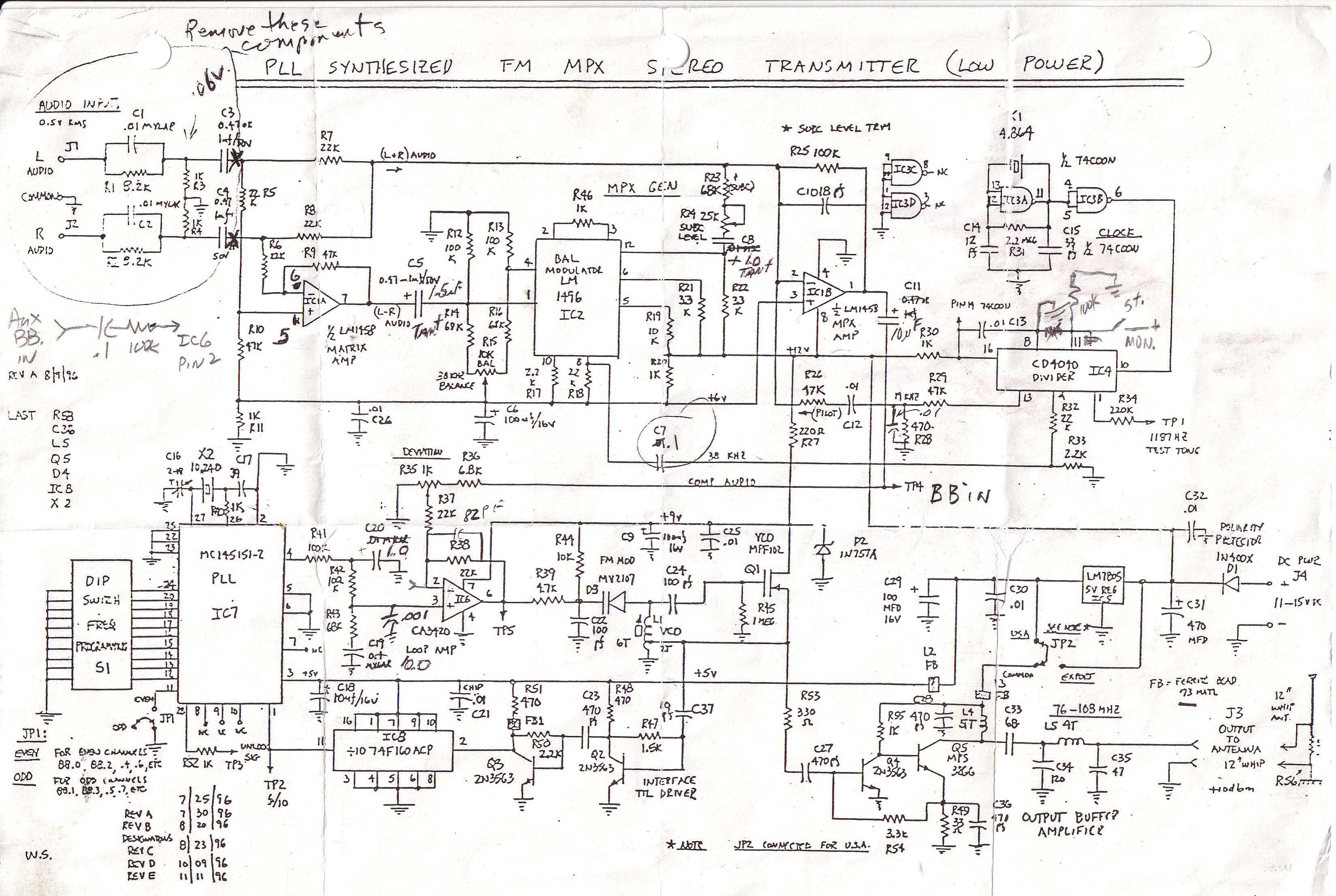
- The problem of poor low-frequency audio response was cured by changing the value of C11 to 10 uF (from the original 1.0 uF), changing C8 to 1.0 uF (from 0.1 uF), changing C5 to 1.5 uF (from .47 uF) and eliminating entirely capacitors C3 and C4 from the audio signal path..
-
The problem of the poorly filtered PLL was cured with the addition of a .001 uF capacitor from pin 3 of IC6 to ground.
-
The PLL damping problem was fixed by changing the values of C19 and C20 to 10 uF and 1.0 uF respectively (from their original values of 0.1 uF and .01 uF).
-
Stereo separation performance was improved almost 20 dB by substituting 1% (22.1k) resistors for R5, R6, R7 and R8 in the circuit and by installing a .1 uF capacitor at C7 in place of the original .01 uF.
Slightly more difficult:
- A mono/stereo mode switch was added as follows (all steps are required):
- Pin 11 of IC4 was isolated from ground by cutting the foil trace between IC4 pins 11 and 8, and between IC4 pin 11 and IC3 pins 1 and 2;
- a jumper was added from IC3 pins 1 and 2 to ground (restores the ground connection to those pins);
- a 100k resistor was added from pin 11 to ground; and
- a wire from pin 11 leading to an off-board SPST switch was added. The switch, when closed, applies +12 volts DC to pin 11. This forces the unit into mono mode.
More hassle, but well worth the effort:
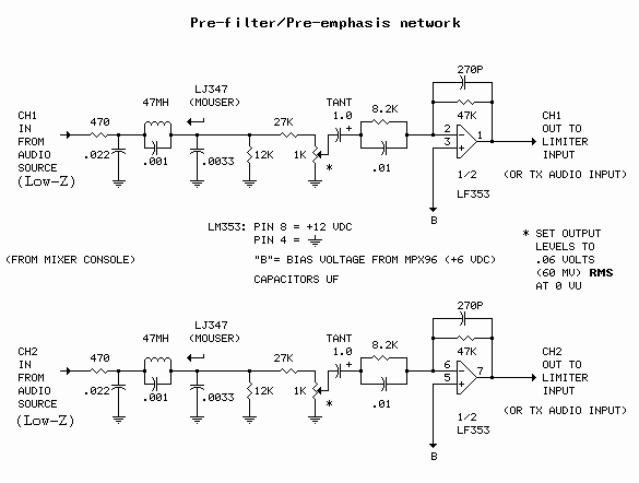
- An external audio filter/pre-emphasis network board was added. This circuit solves two problems by providing both audio input low pass filtering and accurate pre-emphasis. The schematic for the filter/pre-emphasis board is shown in Figure 2.
Figure 2
Note that, for direct connection to the transmitter input (limiter circuit below not used), capacitors C3 and C4 are removed from the MPX96 board and the audio input connections are made directly to the junctions of R5 and R7 (left channel) and R6 and R8 (right channel).
Lots more hassle:
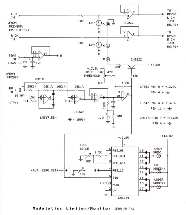
- A relatively complex (for this project) modulation limiter circuit is shown in Figure 3. It responds slowly to average input levels and more quickly to short term peaks, but does not respond instantaneously (because its operation depends on an error signal derived downstream from the gain control portion of the circuit). The limiting action is soft. The limiter will not necessarily prevent overmodulation in the legal sense (75 kHz peak deviation) but does provide leveling and protection from distortion at moderate to high audio input levels. The circuit required quite a bit of fiddling to get right but resulted in a very good sounding transmitter.
Figure 3
The source for the 'BB in' signal input is TP4 on the MPX96. This is the composite 'baseband' signal from summing amp IC6 which directly modulates the transmitter's voltage-controlled carrier oscillator. By sampling the transmitter at this point the entire modulation signal envelope is monitored: the main audio channels (L+R); the sub-carrier signal (L-R); and the 19 kHz pilot. The baseband signal is converted to DC in a high-speed precision rectifier (LM6171BIN), then peak-detected in the following stage. The voltage from the peak detector is fed to LEDs in close proximity to two light-dependent resistors (LDRs) which make up part of a variable attenuator circuit in the audio path preceeding the transmitter input. The LDR's resistance varies inversly with the LED's light intensity, controling the loss through the attenuators. As the signal level, and thus the LED's intensity, increases, the loss through the attenuators increase.
The LM3914 is the 'monitor' portion of the circuit. It monitors the voltage output from the peak detector and drives three LED's. No LEDs lit means no audio signal is being applied; the amber LED lit means an audio signal is being applied but it is of insufficient level to fully modulate the transmitter; the green LED lit means the transmitter is being fully modulated; the red LED lights when the audio input level is too high and the circuit is into limiting mode.
Not necessary, but neat:
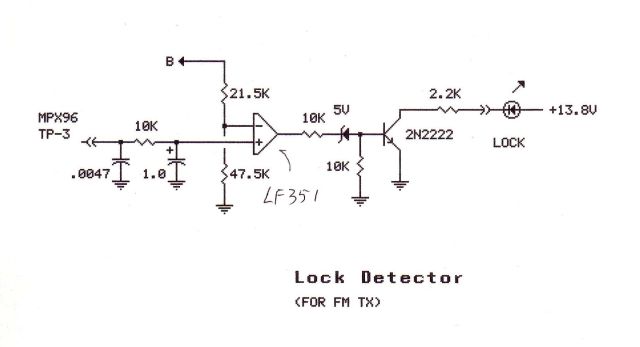
- A "lock" indicator was added. See Figure 4.
Figure 4
This circuit monitors the voltage at TP3 on the MPX96. This is the output from pin 28 of the unit's PLL chip. When the voltage at this point rises above a set point the LED lights, indicating a lock condition. The LED is mounted on the front panal of the exciter/stereo generator and serves as its "power on" indicator.
Two nit pick items, hardly worth mentioning:
- A 82 pF capacitor was installed across R38; a .01 uF capacitor was installed across R28. (Refer back to Figure 1.) These capacitors reduce harmonics of the 19 kHz pilot signal.
-
An LF353 was installed in place of the LM1458 for IC1. The LF353 is a slightly better choice for this application.
Finally, an item useful for testing:
- A direct external connection to the modulator was added. This allows a test tone from an external modulation source to be applied directly to the modulator. This would be useful, for example, in a test setup in which the Bessel null method is used to calibrate a monitor receiver. This mod consists of an added external BNC jack connected to IC6 pin 2 through a .1 uF capacitor and a 100k resistor. (Refer back to Figure 1.)
As of this writing [2006], the MPX96 was still available from North Country Radio. I would recommend all of the above modifications except number 7, the modulation limiter, to anyone building one of these transmitters. You might consider tackling #7 after all of the others are in place and the unit is functioning satisfactorily. See MPX96 Adjustments for setup instructions.
Here are the Figures on this page in printable (PDF) format.
Related Pages:
Comments/Questions:
Latest comments are at the bottom of the file. ↓
Add your comment.
[Mon Apr 3 13:06:33 2006] fmtx.....
Nice set of well thought-out mods! I'm not sure why you used the composite as the point for checking your modulation level. I would have looked at the AUDIO rather than the whole thing. I understand the idea of taking the BB (TP4) signal (after all, it has the sum signal). However, the pilot will surely mess with your overall levels. Perhaps you can compensate with the threshold setting of the limiter.It might also be worth adding a diode clipper after the limiter - it's really brutal, and can sound horrible, but if correctly set will completely prevent overshoot modulationpeaks.
[629]
[Thu Oct 26 20:36:31 2006] catradio.
you are the man, my mpx 96 started hissing and I lost all the schematics and stuff for it, its been so long since I built it I forgot what the adjustments were but found your page and was saved. I use mine to transmit out to the end of the driveway while plowing snow and working around the yard
[309]
[Sat Oct 28 17:09:28 2006] fmtx.....
i have a radio station. my exciter is not producing sound out for broadcast. but the lights indicates that i am get the input. please help me. my station is off now.
[216]
[Tue Oct 29 6:39:15 2010] viewcoms.
I would say that the exciter has failed internally and will have to be repaired or replaced in order to get the station back on the air.
Max
[161]
[Sat Jan 27 01:22:55 2007] fmtx.....
Bonjour! What a super websight! Very refreshing to peruse from where we live in Paris (France). I eat frogs and drink wine. Woold like more informatons on this. Best regards! Mikael.
[202]
[Thu Nov 15 01:21:56 2007] fmtx.....
i am want PCB set modifications MPX96Thank you everymuch
[114]
[Mon Jan 7 16:30:44 2008] fmtx.....
Please send us the PCB design, and the complete part list of of the circuit
[87]
[Tue Jan 8 06:30:59 2008] viewcoms.
I will forward your request to my PCB design guy..
Max
[81]
[Mon Jun 30 23:43:04 2008] fmtx.....
Keep up the good work! It's nice to see stuff like this on the net.
Greetings from a fellow pirate.
[125]
[Tue Jul 1 05:25:05 2008] viewcoms.
Thanks, Fellow Pirate.
Max
[49]
[Sat Jan 23 17:59:17 2010] priv.....
Hi, Max.
I built the MPX96 back in 1998. I've never been totally satisfied with it. I wish I'd had your limiter and indicator design back then when I was first working on it. That would have helped a lot.
Recently, I've improved the reception of other signals in my FM preamp/distribution system by putting a notch filter for two strong local stations in front of the preamp. Other signals (in particular, a weak double-diffracted one only 3 degrees away from the strong pair) are being received well now. That makes me want the MPX96 improved.My only complaint is that it is noisy. The noise is not white or even Gaussian. It has a little "gurgle" to it, and some bass emphasis, but still too much noise at high audio frequencies, too.
The problem is not beats with the 19 kHz pilot, because it is still just as noisy with the audio turned off (a pre-iPod "Personal Jukebox" PJB-100).
The problem is unlikely to be signal-strength related. One of my tuners in the house shows fully limited power on the signal, at least 20 dB higher than some commercial signals that sound pretty good.
I see that I replaced IC1 with an OP275 long ago, probably to reduce noise. My notes also tell me that I had to remove the slug from L1, and put 8.2 pF to ground from the top of L1, to get it to tune to 88.1 MHz.
I am suspicious that the VCO just has too much phase noise with my modification to a (lower Q?) air core L1 inductor.Of course, you don't owe me anything, but I'd appreciate your informed estimate of whether that makes any sense to you. And whether you have any suggestions. Thanks!
My name is Joe Gorin. I live in Santa Rosa, California. My email is jmgorin-2@yahoo.com. I used to live in Loveland, Colorado, not too far from you, in the '70s. I ran a hifi kit company (Symmetric Sound Systems, Inc.) from '78 - '88; I designed about 10 kits during that time, and published most in Radio Electronics. I am still pretty expert at audio, and know a good amount about phase noise and PLLs, but I am clueless about making inductors and some of the practical aspects of RF circuits. I think I followed the L1 build instructions well, even though it didn't work out well.
I didn't send this to the open forum because I didn't see any indication of "community interest" in this topic. If you would like to transfer this message to that forum, I'd have no objection.
[2589]
[Tue Jan 26 13:18:30 2010] viewcoms.
Joe,
Yeah, L1 has always been a problem for builders of the MPX96. The designers probably should have specified a commercially available coil for L1, but they no doubt had their reasons for doing it the way they did.
>> I am suspicious that the VCO just has too much phase noise with my
>> modification to a (lower Q?) air core L1 inductor.
I couldn't say positively, but I don't think so. Adding the capacitor across the inductor would actually lower the loop gain somewhat, which should lower the phase noise, at least phase noise caused by the loop. I don't think your modification would effect the intrinsic phase noise of the oscillator much, if at all. You might try squeezing or stretching the coil to see if that makes any difference. But first..
More likely the noise that you are hearing is an artifact in the modulation signal being presented to the varactor diode. The four sources for that signal are: the correction voltage generated by the PLL (IC7), the L+R audio modulation through pin 2 of IC1b, the L-R sub-carrier from the balanced stereo modulator through pin 3 of IC1b, and the 19 kHz pilot, also through pin 2 of IC1b.
If you've corrected the faults of the loop filter - by incorporating mods 2 and 3 or something of your own design - then the loop filter probably isn't the problem. You can verify that by killing the audio modulation and the pilot. Connect a jumper from R36 (the end connected to the high end of R35) to ground. If the noise goes away, the problem is the L+R audio, L-R sub-carrier, or the pilot (or some combination).
Remove the jumper from R36 and connect a jumper across R28. This will kill the pilot. If the noise goes away, then the pilot, while not necessarily being the source of the noise, is implicated.
Remove the jumper from R28 and connect a jumper across R33. This will kill the stereo sub-carrier. If the noise goes away, then the stereo sub-carrier, while not necessarily being the source of the noise, is implicated.
If the result of any of the above tests is positive, most likely the noise is caused by high frequency artifacts from the audio source mixing with either the pilot or the stereo sub-carrier. You can eliminate the inputs as the source of the problem by disconnecting the audio inputs and/or placing shorting jumpers across R3 and R4. If the noise goes away, then you may have to provide LP filters like the ones shown in Figure 2 if you want to continue using that particular audio source. (The original MPX96 has absolutely no LP filtering on the inputs.)
I'm not aware of any circuit defects in the stereo modulator that would cause a noise problem, but proper adjustment of the sub-carrier level, pilot level and transmitter deviation are very important. If you haven't already, you should carefully make the adjustments shown on the MPX96 "adjustments" page - see: http://maxmcarter.com/fmtx/mpx96adj.html
There is also a possibility that strong RF fields from a nearby transmitter could be causing the noise. Enclosing the MPX96 in a metal box and maybe bypassing the rectifier diodes in the power supply w/.1 uF caps probably would eliminate that.
That's about all I can offer. If you determine conclusively that the audio input source is not the problem, then carefully adjust the sub-carrier and pilot/deviation levels per the instructions. Do that before putting in a great deal of effort modifying the hardware. Then go for the easy mods shown in the web article. Then maybe the coil squeezing, but I don't think that will help much.
Let us know how it turns out.
Regards,
Max
[1171]
[Fri Apr 23 09:42:08 2010] viewcoms.
Do you have any details on the LDR / CdS cells you used in the limiter, such as light or dark resistance? Thanks for the info on this site, you did a good job. Regards, Mike
[194]
[Sat Apr 24 06:14:01 2010] viewcoms.
Thanks Mike,
I think it was All Electronics cat# PRE-12, <100 ohms in full sunlight, >1 megohm in absolute darkness, approx 10 kohm operating in the circuit.
Max
[229]
[Mon Jul 5 19:41:15 2010] viewcoms.
thanks for sharing the informations , It is usefull, i like it!I hope you do better and better on your website,
And popular more and more!
I love the fm transmitter side of things,
and I want to do fm transmitter business!Espacally stereo ,
Maybe you can give me some Suggest,thanks!
http://www.fmheroes.com/
[381]
[Sat Oct 30 10:40:10 2010] viewcoms.
Hi Max,
Your site is not only very interesting to read �the cat Radio� but also inspiring, and very informative and helpful. I hogged each and every piece of information on FM MPX96 that you provided. Pl. keep up the good work.
I had assembled an AM pocket radio, an AM oscillator with 20 feet range a 12watt stereo Amp that was 25 years ago and always wanted to built a Tx and that too a Stereo!
Now I have the time and after reading your site I ventured out and managed to get the MPX96 kit. It is still just the same except a replaced IC6 (TLO81) and 74C00N for IC4 and change in values of R24 from 25K to 100K and R33 from 68k to 33k and I built it with 22.1k 1% R5-8 and 10uf at C11 as per your suggestion. To my surprise it worked the first time! And sound is quite acceptable! Then I put it in a metal enclosure and I used a RF probe (http://www.mycal.net/old/projects/mpr/powerm.htm) to calculate RF power. My DVM displayed .8v RMS. I was very happy. I started thinking of all the modifications that you suggested and got the components and I planned adding a 7W amp if not 14W like yours!
Once in a while I power it up for about an hour with a dummy load and see reaching other end of my apartment. Then built a Dipole and one day with a 10 feet mast I hosted it in my first floor balcony using RG59 from the TV (I did not have RG58 then). I went till about 150 feet away from my apartment it was ecstatic! Clear reception with a pocket radio!
One day I left it on for about 4 hours with a dummy load to do an endurance test. It was fine and was giving 1.2V RMS after about an hour! Then I switched it on next day and to my surprise suddenly the power has gone down to .1v RMS (measured with a 50 Ohm dummy load) and even less. I checked all voltages as suggested in the instruction manual. They are all ok. Collector voltage of Q4, Q5 they are all ok. No shorts in the RG174 that�s connecting RF out at the PCB. I do not have any tools except 2 DVMs and the Rf probe and I cant afford any Oscilloscope or Spectrum Analyser. Now what could be the probable problem? I took the liberty of asking you because you seem very knowledgeable, experienced and very helpful. I would really appreciate any suggestion.
Thank you very much and God bless you.
Hill
[2388]
[Sun Nov 14 07:49:45 2010] viewcoms.
Hello Hill,
Sorry it's taken so long to answer your post - I should be checking this page more often!
Have you verified the transmitter is actually still on the air (check with your little radio) and has the range it did previously? If so, then the problem could be in your RF probe.
Post a reply on this page or, if you'd care to correspond via email, post your email address invisibly here.
Regards,
Max
[534]
[Tue Nov 23 08:51:46 2010] viewcoms.
Hello Max,
Thanks for your response. It's my Thanksgiving gift. Happy Thanks giving.
It's working but it's putting out lesser signal. Earlier with the dummy load on I could receive my MPx96 loud and clear on my pocket radio Grundig YB P2000 from 40 feet, but I did not check how far I could receive the signal from. It has a signal strength indicator of sorts, which use to be on.
But now with the Dummy load on range is about10-15 feet. I have not checked the range with the tuned dipole Antenna that I have built. But again I tried to check the signal through the RF Probe now DVM the reading says 23mV! Which seem nonsensical.
I will check the range with Dipole and let you know. But I am kind of sure that it�s not working as it�s suppose to be.
This is just to update you.
Thanks again and regards,
Hill
[887]
[Sat Aug 20 23:38:03 2011] viewcoms.
Ronnie
hi! sir in what way we can make our mpx 96 fm higher..???
[88]
[Sun Aug 21 05:41:57 2011] viewcoms.
Ronnie,
Higher power requires a power amplifier such as the one shown here. These are available from sources such as Ramsey Electronics and Progressive Concepts, among many others.
Higher frequency would require redesign of the MPX96 circuitry - probably not practical.
Max
[221]
[Fri Sep 23 19:50:51 2011] viewcoms.
Good day sir,
Can we ask how much is the amplifier to make our mpx96 higher..???to whom /Where we will send the money to buy that amplifier?I�m Ronnie Dinglasa from San Jose Manjuyod,Negros Oriental Philippines.
Thank�s and God bless�
[313]
[Sat Sep 24 05:18:39 2011] viewcoms.
Hi Ronnie,
I don't know. The power amp shown on this site is not available for purchase. It's a homemade job built with surplus components as described (in a general way) in this article. I suggest you check the links mentioned above or Google something like FM power amplifier or LPFM amplifier. I'm not in the business of selling amplifiers.
I hope this is helpful.
Regards,
Max
[375]
[Sun Oct 2 01:33:51 2011] viewcoms.
thank's a lot sir
[29]
[Sat Jan 26 02:32:01 2013] viewcoms.
Hello Max,
It's long time. I will email you.
In the meanwhile please help me understand why my Lock detector does not work. The LED lights up without connecting 21.5k to "B" and without connecting to pin 28 of LSI (TP3). As soon as I take out the 351 IC from it's socket the LED stops lighting. Could the 351 be bad? Also, I have 47K instead of 47.5K and 22K instead of 21.5K in the -ve (inverted) pin. Does it make any difference? Also does it matter that I have 2N2222A in place on 2N2222 ? Pl. Help me out. Thanks and regards,
Hill
[590]
[Sat Jan 26 05:53:19 2013] viewcoms.
Hi again Hill,
Check the voltage on pin 2. It should be approximately 4 volts. If not, check the voltage at B. It should be about 6-7 volts. If that's OK, verify the resistor values 47k and 22K. It's OK to play with the values of those resistors. The values shown were selected assuming 6 volts at B. If the B voltage is on the high side, the values shown may not work. Try a 27k or 33k in place of the 22k.
If the voltage on pin 2 is OK, check the voltage on pin 3. It should be around 5 volts when IC7 is locked. If not, there may be a problem with the 10k resistor or the capacitors.
Also, check the voltage on pin 28 of IC7. Should be around 5 volts when IC7 is locked.
If that's OK, look for a wiring error, short circuit, etc.
Hope this helps. Let me know what you find.
Regards,
Max
[912]
[Sun Jul 27 03:19:13 2014] fmtx.....
Hi...
how to configure the premphasis to 50us in your modifications?
I assume that your preemphasis are 75us
Regards,
AN
[168]
[Mon Jul 28 05:21:23 2014] fmtx.....
AN,
Changing the value of the 8.2k resistors connected to the inverting pins (2 and 6) of the LF353 op amps to 5.6k should do the trick.
Regards,
Max
[190]
[Wed Aug 13 10:52:48 2014] fmtx.....
Hi Max,..
Thank for the trick...
What the collector voltage of Q2 and Q3?
Q2 and Q3 voltage of my mpx96:
Q2 - 0.9 Volt
Q3 - 1.5 Volt
Regards,
AN
[223]
[Fri Aug 15 05:22:49 2014] fmtx.....
AN,
Sounds about right. I will check my MPX96 and post the readings soon.
Max
[112]
[Tue Aug 26 09:39:21 2014] fmtx.....
Hi Max,..
Thanks for your help..
I Forgot connecting pin 25 of IC7 to ground...(the PCB is self made) I was think that Q2 and Q3 is the problem.
My PLL is now work... When I adjust L1 Voltage range at TP5 between 2.9 - 8.3 Volt.
Regards,
AN
[302]
[Wed Aug 27 05:00:51 2014] fmtx.....
Hey great, AN! Glad you got the circuit up and running!
Max
[84]
[Tue Oct 8 18:33:12 2019] fmtx.....
[The following shows a few snipets edited from 22 posts from Bill. The posts refered to a (non-MPX96) transmitter he designed but was not happy with. Bill had trouble collecting his thoughts. My comment (following) addresses some of what he was trying to say, I think. - Max]
Ok lets see? Hum? Max, My name is Bill.
...distortion of modulated design from poor quality exciter design.
I bought a microprocessor designed to generate FM Stereo. I have been for the last 15 years decoding the source of the distortions. The quality of FM stereo modulators are many, but mostly the sine wave distortion of any frequency, say the 38 kHz carrier suppressed? The noise observed has all to do with the quality of the multiplex modulator 38 kHz mixer carrier noise.
I found the IC I used to generate the 19 kHz pilot was ok, but the 38 kHz was distorted.
[29]
[Fri Oct 18 07:21:48 2019] fmtx.....
Glad you got your transmitter working to your satisfaction, Bill; sounds like it was a struggle. For what it's worth, the 38 kHz carrier in the MPX96 is a squarewave. That carrier is effectively nulled out in balanced modulator IC2 when it's properly adjusted and does not appear at the input to the FM modulator.
The MPX96 had some faults, as noted in the article above, which the mods cleared up nicely. As also noted, deriving maximum benefit from the circuit requires knowledge of the principles involved, plus patience and test equipment. The result looks good on the scope and, to my ears, sounds as good as anything out there.
Max
[13]
[Mon Feb 3 22:48:32 2020] fmtx.....
www.onsemi.com/pub/Collateral/AN531-D.PDF
Please start with this PDF for reference.
Read introduction down to device operation, closely. (note text goes from bottom left to top right on each page). The very first paragraph of DEVICE OPERATION tells it all. Your' quote that your' modulator sound good with no distortion, likely is because you have your' unit tuned correctly! But there is a very large margin of error possible, in the design, giving rise to users not getting the proper mix between Vx & Vy, in the MC1496, resulting in high distortion. The simple solution to the problem, is to supply enough Vx (38khz) drive to pin 8 of BM, to saturate the BM Q1, Q2, Q3, & Q4. This will guarantee linear translation of the -(L+R) to 38 khz DSB suppressed carrier. One possible solution is to adjust the attenuation between IC4-4 & IC2-8 for maximum drive, (remember this path is phase sensitive reference the Pilot phase, & the Pilot phase is 12 as sensitive to phase shift in the Pilot signal path with the composit). Give enough drive signal to saturate Vx in the BM, will eliminat the possible error in the VxVy ratio with too much Vy drive, not enough Vx drive. I may not be totally right all of the time, but I am never totally wrong! Obviously if the -(L+R) drive is low enough, it will not saturate the low BM Vx drive, but then it may not be in composit balance, with the L+R at the receiver mpx detector, resulting in reduced seperation. My designs give me 50dB to 55dB seperation from a LA3390 pll mpx receive, @ 1kHz. What is the separation of your' unit Properly tuned of course. It should be close to 50dB, if it is tuned correctly, & functioning correctly at the BM, & using a good Pll mpx receiver!
I hope this is some help to you, Max. Good luck, & Happy New Years. Bill.
[2157]
[Tue Feb 4 08:18:13 2020] fmtx.....
Thanks Bill,
Yep, the good old '1496 balanced modulator.
You put your finger on it. By substituting a .1 uF for the original .01 uF at C7, the 38 kHz carrier amplitude on pin 8 was increased slightly and its phase brought into closer alignment with the 19 kHz pilot.
Replacing R5, R6, R7, R8 and C7 (mod #4) improved stereo separation by 20 dB, putting it somewhere north of 50 dB. I don't recall exactly how I measured it, probably with my Heathkit AJ-15 tuner, which I had carefully aligned and calibrated using an IFR service monitor from work.
Regards,
Max
[418]
[Fri Mar 20 08:11:09 2020] fmtx.....
I suggest using the BA1404 for the total ball of wax to replace your present distorted design with ultra high tech design of the BA1404, because it is difficult at best to preset all of the linear levels needed with the MC1496 to function correctly as a 'phase linear translator'
Everything is done for you in the BA1404, right down to the absolute phase relationship of the 19k with the 38k phases for maximum separation quality.
[460]
[Fri Mar 20 08:21:16 2020] fmtx.....
There seems to be some confusion here. The MPX96 was not designed by me. It was designed by Rudolfe F. Graf and William Sheets, owners of North Country Radio, in the mid 1990s. I bought the kit from NCR in the late 90's after fooling with a Ramsey kit that I never could get to work to my satisfaction. [It may have incorporated the BA1404. I don't recall.] I soon found that the MPX96 was not perfect either. But it was straightforward, i.e., not a "single-chip" design. The functions - RF carrier generator, FM modulator, subcarrier/pilot generator, balanced L-R modulator, etc. - were separate. The problems could be dealt with individually. I proceeded to tackle the issues, one by one, until the unit achieved perfection (at least to my ears). Six years or so later, after starting this web site, I decided to publish my experiences with the MPX96. And now, fifteen years later still (today), the unit continues to operate 24 hours a day at 100 mW, and intermittently during the Christmas season at 14 watts. So no, after 21+ years of flawless operation, I will not be redesigning the MPX96.
Max
[13]
[Thu Nov 26 15:32:48 2020] fmtx.....
Hello and Happy Thanksgiving!
Could you please post the instructions for setting the dip switches for frequency adjustment?
Thanks, Bill
[174]
[Fri Nov 27 09:48:17 2020] fmtx.....
Happy TG to you too, Bill!
I couldn't find programming instructions with the original documentation, so had to figure it out from my as-built MPX96.
For programming instructions, click: here.
Let me know if it works!
Max
[13]
[Tue Jun 28 16:12:43 2022] fmtx.....
Hello Max, your web page really inspires creativity, excellent modifications in the tx mpx98, I have tried them and they work very well, thanks for your contribution, from La Pampa Argentina Greetings Gabriel.
[242]
[Wed Jun 29 05:01:55 2022] fmtx.....
Thanks, Gabriel!
Max
[45]
[Fri Jun 21 15:07:04 2024] fmtx.....
Dear Mr Carter
may i ask you something:
I am searching for Software for MPX2000 with PIC16F84 from North Country Radio.
Can you tell where i can get it?
Markus
[193]
[Tue Jul 9 05:00:15 2024] fmtx.....
I can't help you on that, Markus. Sorry. :(
Max
[89]
Scroll up ↑ to view previous comments.
Add Your Comment
Type your comment or question in the box below and click SEND.
(No links, no HTML.)
Top of page. ↑ Top of comments. ↑
|
|