Don't want to build the stepper motor synchroscope?
Want more color in your life?
Build the
LEDscope
An Alternative Indicator for the WWVB-Based Precision Frequency Comparator
|
While the I and Q LEDs are interesting to watch and provide an indication that "something is going on", they have limited usefulness for actually monitoring and/or adjusting a frequency standard. This circuit add-on improves on the bare-bones I/Q indicators by providing a sense of direction - an indication of whether the frequency of the standard being monitored is too high or too low. Conversely, it tells what direction (up or down) an oscillator should be adjusted in order to correct its frequency. While this indicator does not have the resolution of the stepper motor and pointer, it provides a quick and dirty means of monitoring, characterizing and adjusting a frequency standard. If one watches the LEDscope for at least 10 seconds, the frequency of a 10 MHz standard can be verified to better than 1 Hz (.00001%). Watch it for 100+ seconds and the accuracy jumps to better than 0.1 Hz (.000001%). The LEDscope can be used alone: No stepper motor, I/Q LEDs, computer or oscilloscope are required.
The schematic for the LEDscope is shown below:
LEDscope Schematic
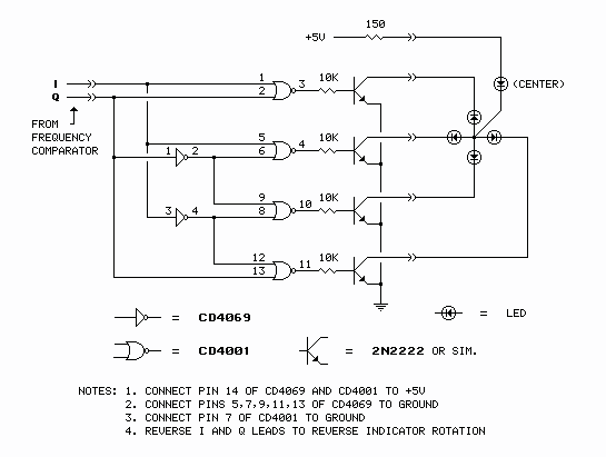
The circuit is a simple decoder. It converts the 2-line gray-code I and Q signals to a 4-line output, with each output line driving one of four LEDs evenly spaced in a circle. The LEDs are lit sequentially as the phase error slips are generated by the phase comparator circuits of the Frequency Comparator.
My implementation of the LEDscope display is shown in the photo below. As you can see, it's been incorporated into the stepper motor/pointer/old clock face synchroscope shown in the original article.
The LEDscope Display
The four outside LEDs are the indicators.
The yellow LED in the center (always lit) provides a "hub" for the indicator LEDs to "rotate" around.
The yellow LED makes it easier to interpret the display at a distance.
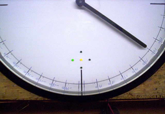
The direction of rotation indicates whether the oscillator being monitored is above or below its nominal frequency. Typically, clockwise rotation will indicate the oscillator is above nominal; counter-clockwise rotation will indicate the oscillator is below nominal. The direction of rotation can be reversed by reversing the I and Q inputs.
The speed of rotation indicates the frequency error (offset) factor. Error factor is calculated the same as with the stepper motor synchroscope:
Frequency Error Factor = dNφ/dt = dN x 1/1000000 x 1/dt.
Thus, for example, 1 step per second indicates an offset of 1/106 [1 x 1/1000000 x 1/1]; one step in 10 seconds indicates 1/107; one step in 100 seconds 1/108, etc. The procedure for adjusting a frequency standard using the LEDscope is the same as with the synchroscope: Adjust the frequency against the offset indicated by the rotation of LEDs. Adjust in small increments. Adjust for minimum offset or until the desired offset is acheived.
WWVB-Based Precision Frequency Comparator
WWVB-Based Precision Frequency Comparator - Computer Interfaced Version
Frequency Controller - Add-On Circuit Discliplines Ovenized Crystal Oscillator
