Old Receiver Adapted to New Signal
2012 WWVB Receiver Modification
Modification makes homebrew receiver insensitive to WWVB's new biphase-shifted time code.
For more on this receiver, see: WWVB-Based Precision Frequency Comparator
See also below for some thoughts on how to modify some commercial WWVB receivers.
Max Carter
Early in the year 2012 WWVB began occasional on-air testing of a new binary phase-shift keyed (BPSK) time code transmitted simultaneously with the original amplitude-modulated code. The new code became a permanent part of the format in late 2012. See: Wikipedia - WWVB.
The new time data is encoded in 180-degree phase shifts of WWVB's 60 kHz carrier. Because of the shifting phase, my homebrew WWVB receiver was unable to lock to the carrier during periods when the biphase modulation was being tested, even though a very strong signal was being received. When the phase-shifted code became permanent the receiver would have been rendered permanently inoperative, unless...
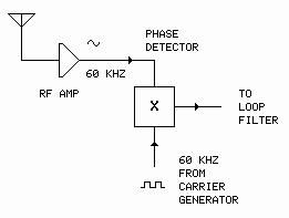
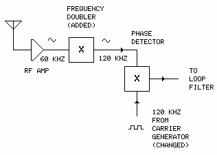
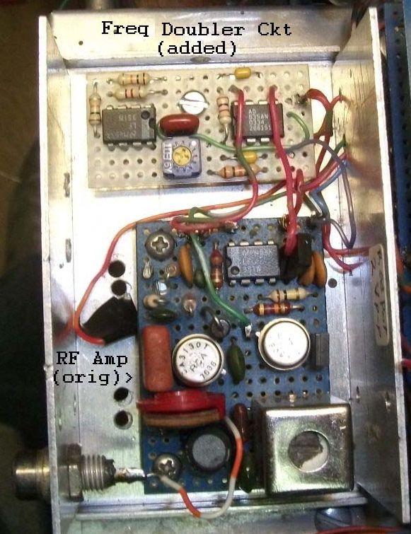
It was obvious that for continued operation, the receiver would have to be redesigned or modified - changed in a fundamental way for the first time in 30 years. Modification was the easiest route: The circuit was changed by adding a frequency doubler - AD835N 4-quadrant multiplier chip - between the output of the RF amplifier stage and the phase detector circuitry. The receiver's carrier generator was also reprogrammed to double its frequency. The changes are shown below:
Circuit Before Modification
After Modification
Frequency Doubler (Squarer)
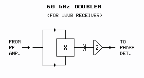
The AD835 could be thought of as an analog computer with two inputs. The chip multiplies the voltage at one input with the voltage on the other. By feeding identical signals to the two inputs the signal is "squared" (multiplied by itself). The result is that the input signal frequency is doubled. A sometimes useful side-effect of the squaring process is that a DC offset is acquired (a negative voltage squared becomes positive). In this case the DC offset is not desired. The output of the AD835 is AC-coupled to restore the signal baseline to zero volts (ground potential). The doubler circuit is shown below:
Figure 1
Frequency Doubler Circuit
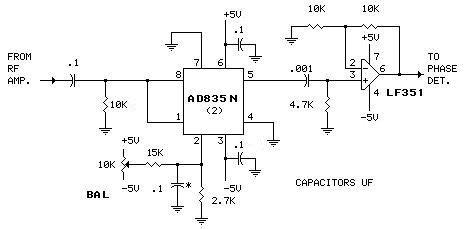
Important Note: The circuit drawing (Fig 1) has changed slightly from the previously published version with the addition of a .1 µF cap and 10k resistor ahead of the AD835 multiplier chip. This restores the signal baseline to zero volts (ground potential). The change does not affect the circuit's function. If you would like to use the circuit in your application, please use this version.
[The less-expensive AD633 would probably work in this circuit, though the pinouts, biasing and power supply requirements are different. (May require an auxiliary power supply.) Consult the datasheet.]
Note: BAL (balance) is adjusted for best sinewave output symmetry (LF351, pin 6). If you do not have access to an oscilloscope, eliminate the 10k pot, 15k resistor .1 uF capacitor (*) and 2.7k resistor; ground pin 2.
After addition of the doubler circuit the 180° carrier phase shifts (now 360°) are virtually invisible to the receiver's phase detector. The conversion gain (Kφ) of the phase detector is increased somewhat (and thus system loop gain), but it doesn't seem to affect the operation of the overall system much. The receiver now goes a little berserk at the ±45° shifts at minutes 10 and 15, but settles quickly. [It appears the ±45° shift is not included when the BPSK code is being transmitted. Good!] Otherwise the receiver now chugs along as before. [WWVB has tweaked the phase reversals since early testing so as to make the BPSK code even less apparent to the modified receiver.] Decoding of the amplitude-modulated original time data also resumed after the modification. [I have no plans to add biphase time code recovery capability to the receiver, though it would be an interesting exercise.] The modified receiver will continue to be useful as a frequency standard, as it has for the last 30 years.
Photo
Note 1970's technology / homebrew construction.
Addendum 1: Receiver Front-End
In response to a couple of queries from readers about the WWVB receiver's RF amplifier and AGC circuit, I've decided to include a schematic of that circuit here in case someone else is interested. Because all of the original documentation has been lost, I had to back-engineer the thing a little in order obtain enough information to allow installation of the frequency doubler circuit described above. The RF amplifier/AGC circuit appears below.
Figure 2
RF Amplifier
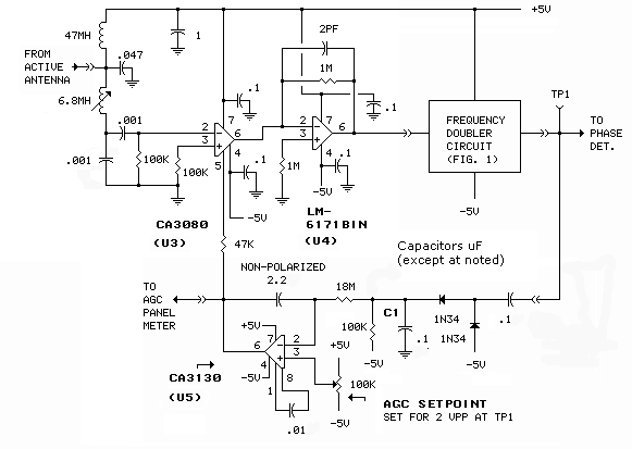
Current-controlled amplifier - U3 & U4
The key to the circuit's operation is U3, a CA3080 transconductance amplifier. Combined with U4, LM6171 opamp, the pair provides something like -20 to +60 dB of variable (current-controlled) gain. U3 is not a voltage amplifier; it must be combined with the LM6171 (or similar fairly high-speed opamp) to provide voltage gain. The gain of the pair is controlled by U5, the AGC amplifier. A more-positive output from the AGC amp drives more current into pin 5 of the CA3080, generating more gain in the CA3080/LM6171 pair. The circuit originally had an LM318 in the U4 spot. The LM6171 is less fussy than the 318.
The tuned input circuit (6.8mH inductor, 001µF capacitor), along with a similar circuit in the active antenna, provides only modest selectivity at 60 kHz. The receiver's extremely narrow bandwidth (<1Hz) is provided by the loop filter downstream.
AGC amplifier - U5
The two 1N34 diodes, along with the .1 uF capacitors and 100k resistor, form an envelope detector. The rectified input signal voltage appears on C1. This voltage is amplified by U5, the output of which controls the gain of U3 through the 47k resistor. The response time of the AGC amplifier is very slow - the circuit acts as an averaging detector, even with WWVB's very slow modulation. That long time constant makes the AGC circuit (almost) impervious to short noise spikes.
Addendum 2: And the Rest of the Receiver??
Unfortunately, back-engineering the front end did not include the balance of the receiver downstream from the RF amplifier/frequency doubler. The general layout is shown below.
Phase Detector/Loop Filter/VCXO/Carrier Generator
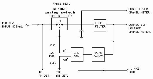
The phase detector in the receiver is a sampling type and operates in linear mode - unsaturated. That type detector, combined with the AGC-controlled front end, is less susceptible to random noise and signal amplitude variations. As the input signal gets noisier, ie, the signal amplitude decreases relative to noise, the detector's conversion gain goes down and loop bandwidth automatically narrows.
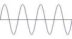
The shots below show the operation of the phase detector. The system is locked to the incoming signal as shown.
|
Phase Detector In | Phase Detector Out |
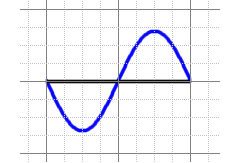 | 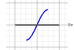 |
The detector converts the phase of the incoming signal - relative to the locally-generated carrier - to a voltage.
I don't remember specifics on the loop filter, except that I used Howard M. Berlin's Design of Phase-Locked Loops with Experiments (H.W. Sams, 1978) as a design guide. The filter is a damped low-pass type - strictly analog, consisting of resistors, capacitors and an opamp or two. It's a "two-speed" affair. It comes up in 'wide' mode for quick lock, then switches to narrow when lock is achieved. At such time as loss of lock is detected, it switches back to wide. [The loss of lock situation will occur when WWVB occasionally goes off air.] The loss-of-lock indication, OR'd with a complimentary loss-of-signal indication from the receiver's synchronous amplitude detector (part of the time-code recovery part of the receiver), lights an indicator LED on the front panel and issues a TTL-level "loss-of-carrier" signal through a connector on the rear panel.
The DC output of the loop filter is compared to zero reference (ground) and the difference voltage is highly amplified. The loop filter/amplifier output voltage varies the frequency of VCXO. The system operates isochronously: The frequency of the VCXO/carrier generator is driven by the loop amplifier so as to produce zero net volts on the sampling capacitor at the output of the phase detector (zero net phase error).
The VCXO is a simple TTL-based crystal oscillator (from Poly Paks - anybody remember Poly Paks?) with a varactor diode added across one of the frequency trimming capacitors. That thing has exhibited remarkably little long term drift over the years - I may have re-adjusted it twice in 30 years. It does exhibit some variation due to changes in ambient temperature, but being in a disciplined environment (in the loop), it matters little.
The carrier generator is made up with CMOS counters and CD4046 phase-locked loop ICs, the exact details of which have faded from memory. Back engineering that part of the receiver would require a major tear-down and, barring a failure which would require going in to affect repairs, probably won't happen.
The receiver also has the capability to recover WWVB's amplitude-shifted time code. The time code is used by millions of radio-controlled clocks around North America to stay synchronized. The time (UTC or local) is displayed on the front panel. [Since a radio-controlled clock can be had relatively cheaply nowadays, this function has been rendered redundant, though I would like to think this receiver, with its synchronous AM detector, would out-perform the el-cheapos in difficult situations.]
Synchronous AM Detector
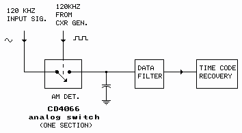
The front panel also includes lots of other lights, switches and meters (phase error, correction voltage, AGC), including a display of the shift register that receives the time code. For a photo click one of the links below.
From Comments/Questions
[Sun Mar 23 17:12:23 2014] wwvb.....Hi Max,
I have an old Tracor 599 phase lock receiver that used to work well. I have calibrated my frequency standard with it and the standard now has excellent accuracy. However since WWVB changed to phase shifting, the Tracor will not lock. Do you think your modification will work on it?
Best regards,
John Reed, KA5QEP
[365]
[Mon Mar 24 05:38:26 2014] viewcoms.
John,
In principle, yes. It would require a study of the receiver's circuitry to determine where to install the doubler (Figure 1). A tougher issue would be reconfiguring the local carrier generator to produce 120 kHz. It might be simple; it might not be so simple. Without the receiver's circuit schematic/service manual, it would require back-engineering.
I'm not familiar with the receiver, but it's unfortunate that what looks like a fine old piece of gear suddenly becomes a boat anchor. Don't toss it out though. You never know. Someone might figure out a modification.
Regards,
Max
[652]
[Sat Dec 5 13:12:22 2015] wwvb.....
Hi All,
Thanks for your material on WWVB. Inspired by this, I modified my Spectracom 8161 successfully. I tried out with good results the MC1496 and the AD633 as frequency doublers. I modified the reference tripler to work from 40khz to 120khz. Anyways, the unit is working properly and it appears to function as well as it before the WWVB change. The TCODE also works as expected. I may use a small uC tu re- insert the hourly phase markers as I use a chart recorder for phase tracking.
73s,
Gerhard, VE6AQO
[557]
[Sun Oct 6 05:03:00 2024] viewcoms.
Hi Max%2C%0D%0A%0D%0AAny thoughts on a circuit using the MC1496 instead of the AD633/AD835 as the MC1496 can be had in SMT for about one dollar from Mouser. This would be a huge cost savings. I would like to modify my 8163 to use this. I would be willing to lay out a PCB for such a circuit. Thank you %26 73 Sam W3OHM
[339]
[Sun Oct 6 05:33:23 2024] viewcoms.
[More on Spectracom modification]
Sam,
One poster [Gerhard, VE6AQO] mentioned using a MC1496 and AD633, also mentioning that he reconfigured the reference source to 40 kHz, tripled to 120 kHz. You might try contacting him for the details. My recollection is that the "local" input node of the chip [pin 8] is typically a square wave or driven into saturation, but I'm not sure that's a hard and fast requirement. If so, it would make it unusable as the "RF" doubler. I was attracted to the AD835 because of it's linear nature and easy implementation. Yes, expensive!
Max
[600]
[Tue Nov 22 09:24:14 2016] viewcoms.
Truetime Model 60-DC - 2012 WWVB Modification
Max,
I was very inspired by your write-up on the method in which you modified your receiver for the new WWVB signal. My father has an Truetime Model 60-DC WWVB receiver that is a great piece of old (phase locking) equipment. Of course it stopped working after 2012. It was a MAJOR disappointment to him and as his retirement gift, I wanted to find a way to modify it so it could work again. It would mean the world to him! This is how I stumbled on your write-up. I have a basic understanding of electronics and have designed a few basic circuits myself, but I'm no where near your level. I am at a loss on how to go about this on the Truetime 60-DC. I was wondering if you wouldn't mind glancing at the manual for the 60-DC and telling me if you think it's possible, using your method of squaring the signal. I have a link to the manual (but can't post a link on your comments page).
ANY help you could provide would be appreciated more than you know! Please e-mail me ANY time, I can send you the link to the manual.
John (W6GFY)
[1182]
[Thu Mar 23 21:06:17 2017] viewcoms.
Max, thank you for your article on WWVB Receiver Modification. Those AD835s are pricey but I bit the bullet and using your suggestions, I've been able to get my Truetime DC-60 going again.
One thing that I've noticed, however, is that your additional modification (replacing the 10k resistor with 100k and piggybacking 2.2Mohm across the 680k resistor) does not work for me. The AGC voltage drops to -220mV and completely shuts down the input amplifier... once those parts are restored to their original values, the AGC goes back up to about -45mV and I'm "hearing" the WWVB once again.
Keep in mind that I have one of the original DC-60's running here with board numbers starting with 85-...
I'm located in the Toronto, Ontario area and normally the WWVB signal here is around -70 to -75 dBm. I'm curious if this modification change was intended for those living closer to Ft. Collins?
Anyway, bottom line is I'm happy my DC-60 is working once again. Thank you once again.
vy 73
Alex VE3GOP
[1075]
[Fri Mar 24 05:49:51 2017] viewcoms.
Very interesting, Alex!
Yes, that is precisely the case, though maybe for a slightly different reason. WWVB radically upped its radiated power about 10 years ago. My correspondent John W, located in California, experienced the overload problem described. In that case the revised version of the mod shown on the web page was beneficial.
I suscpect you would have been OK simply clipping out the 2.2 meg resistor, but hey, you can't knock success! Glad you were able to get your 60-DC up and running, and thanks for your feedback. You've passed on some very useful information!
Max
[586]
[Sun Sep 17 19:03:32 2017] viewcoms.
Hi - thank you for your information about WWVB timing receivers. I was just given a True Time 60-TFR; is there any chance you might have a link to a manual or other documentation? Alternatively, do you know anyone looking for one?
[250]
[Mon Sep 18 05:32:03 2017] viewcoms.
I don't have any information on that receiver. You might drop a note to John van Groos. His dad was president of True Time. johnwvg at gee mail etc.
Max
[178]
[Thu Sep 21 00:49:20 2017] viewcoms.
Hi Max,
John did not have a manual but had some very interesting product descriptions and specs. I am finding it harder to think of getting rid of the 60-TFR and easier to think of modifying it, especially with the increased WWVB power level making antenna construction easier. Rather than doing all the work at 120 KHz what do you think of following an analog squarer with an analog square rooter so that all the work is done at the original frequency?
Andrew
[500]
[Thu Sep 21 07:30:31 2017] viewcoms.
Hi Andrew,
Without knowing the internals of the 60-TFR, it's hard to say for sure. Modification of the carrier generator in the 60-DC was relatively trivial, requiring only a bit of rewiring to make it produce 120 kHz. I did explore the idea of following the squarer with an analog divide-by-two. In addition to requiring a second multiplier chip and associated components, the circuit turned out to be way too fussy. (I hadn't thought of the square rooter.) The trick is maintaining the amplitude modulated time data riding on the signal through the processes. If you decide to pursue the idea I would be interested to see the results of your efforts.
Max
[645]
Schematics produced with DCCAD.
